First Huge thanks to JohnH Here on the forum. He sent me his brand new ASCO Valve Manifold for review.
First let me say this thing is a monster ha-ha
Let we walk you through the pictures,
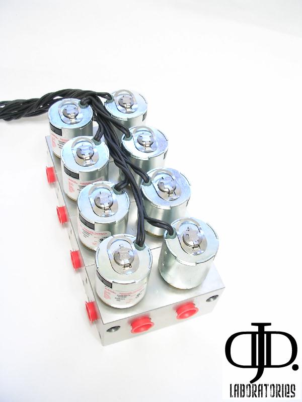
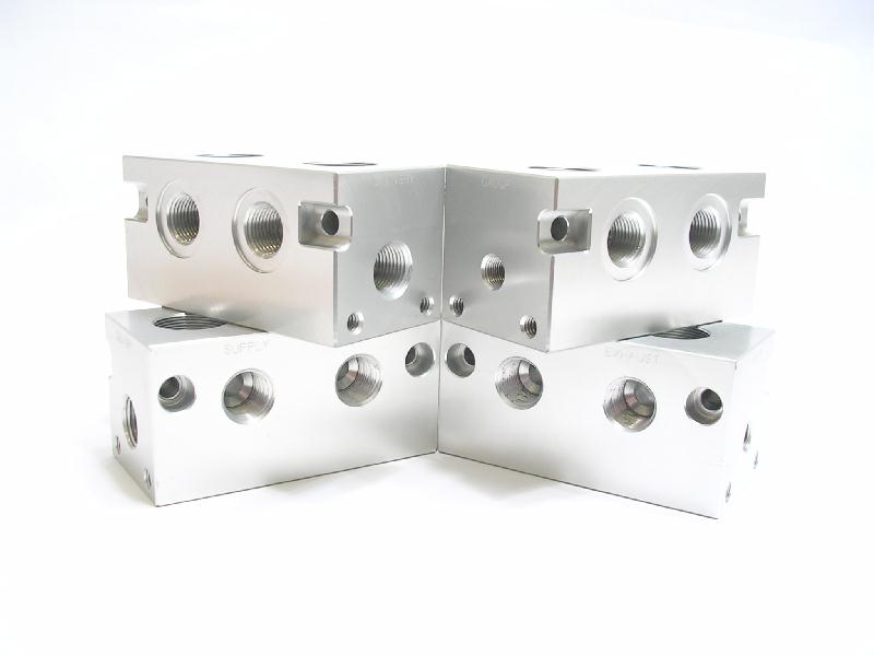
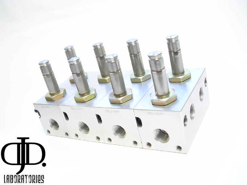
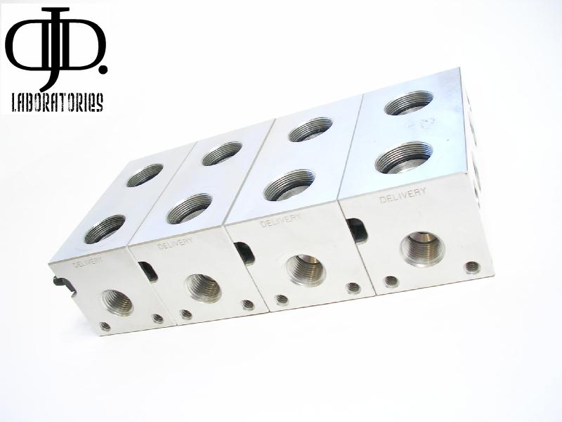
The Valve is a big block of shine!
Almost every part but the wires have a shine to them.
The one hard thing is the wires. Trying to keep all of the wires looking clean is tricky. I found if you twist wrap each coil individually then twist each next pair together and so on you will end up with a fairly clean installation. If you are so motivated you could braid them tougher or Zip tie.
Like I said before this valve is Beefy!
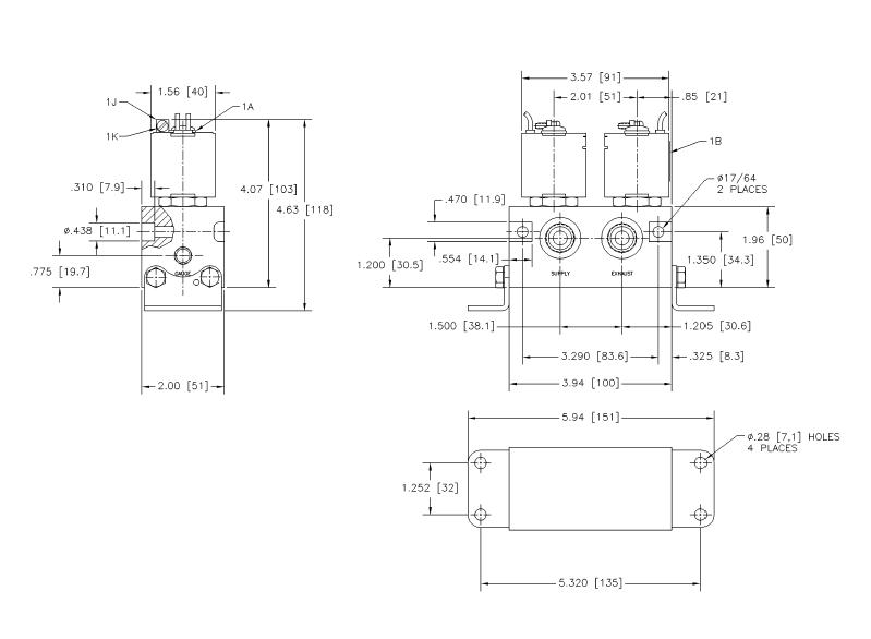
Weighing in at just under 10lbs and 8” long 4” wide and an impressive 4” tall.
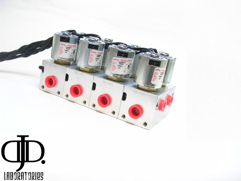
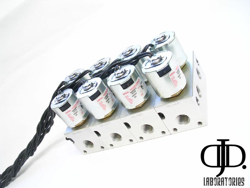
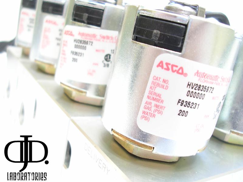
On interesting thing (Nit picky I know) only 4 of the solenoid coils have labels. For some that means only 4 to remove
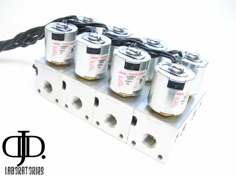
But keep this in mind when you take the valve apart so you can keep the look uniform.
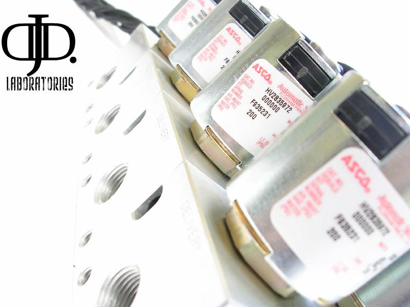
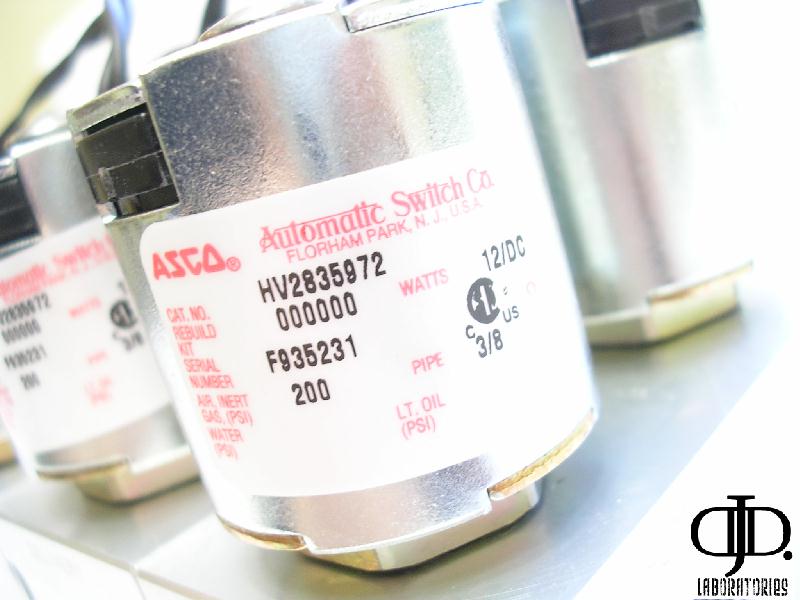
Here is more information on the valve itself (not the manifold)
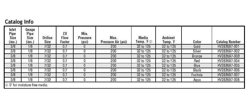
It is ratted for 200PSI and is a 3/8 equivalent valve.
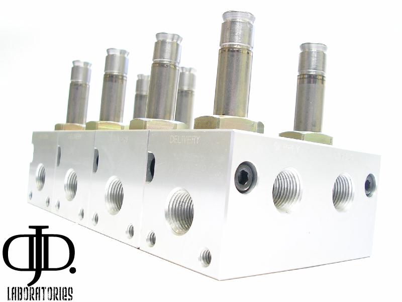
Again this may be nit picky, but the valve stems are not all plumb or level to the base some shoot off at different angles.
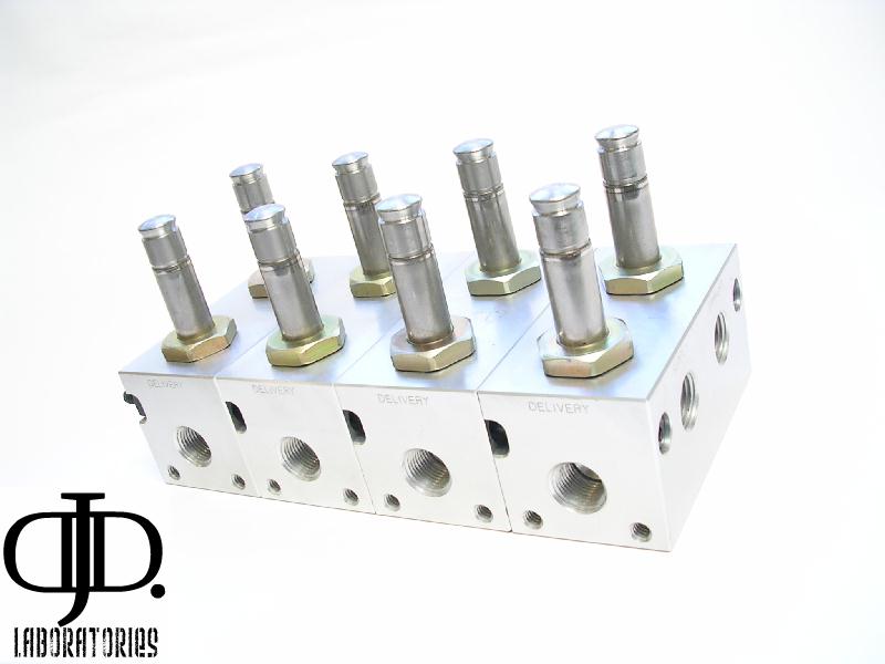
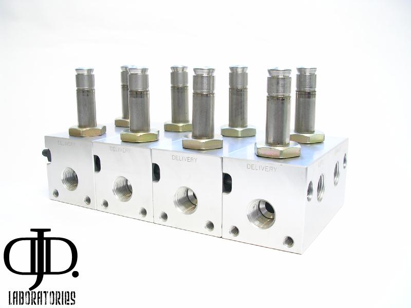
As you can tell here the valve is made up of multiple segments (I will go further into this later)
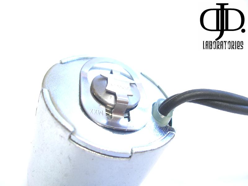
This is my favorite feature of this valve.
The coil retention clip is a really neat design
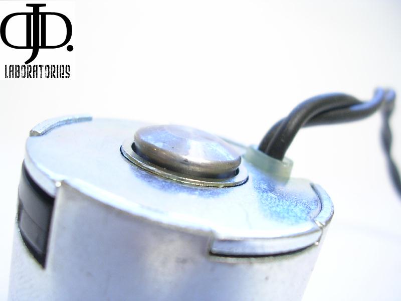
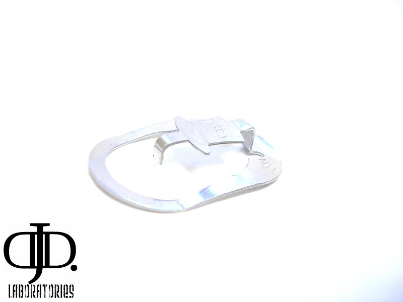
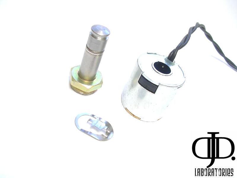
There is no way for this clip to ‘pop’ off unexpected you have to lift up on the little ‘hat’ tab then press the clip back and it will spring off. A nice piece of mind. This clip also holds the coils snugly in place no loose play or coil spinning freely.
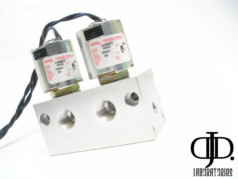
As I explained earlier the valve is built out of 4 smaller segments. These segments can be disassembled into smaller valve groups. For example if you wanted to mount the valve body close to each bag or speed up operation by running a separate line to each valve group.
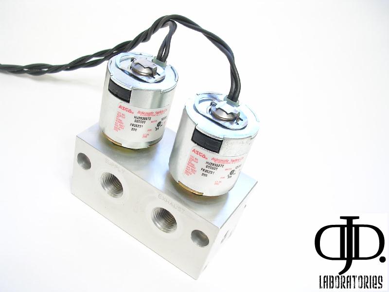
Being a new valve I found a few things that did bother me,
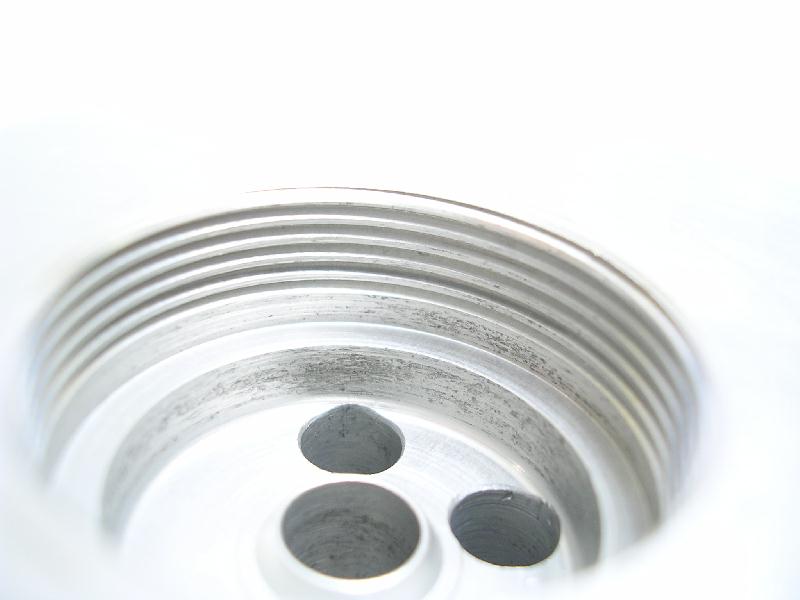
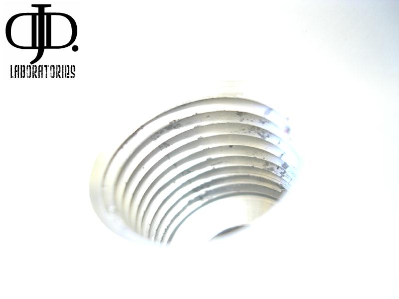
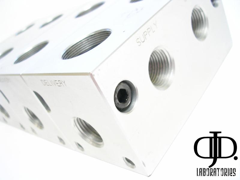
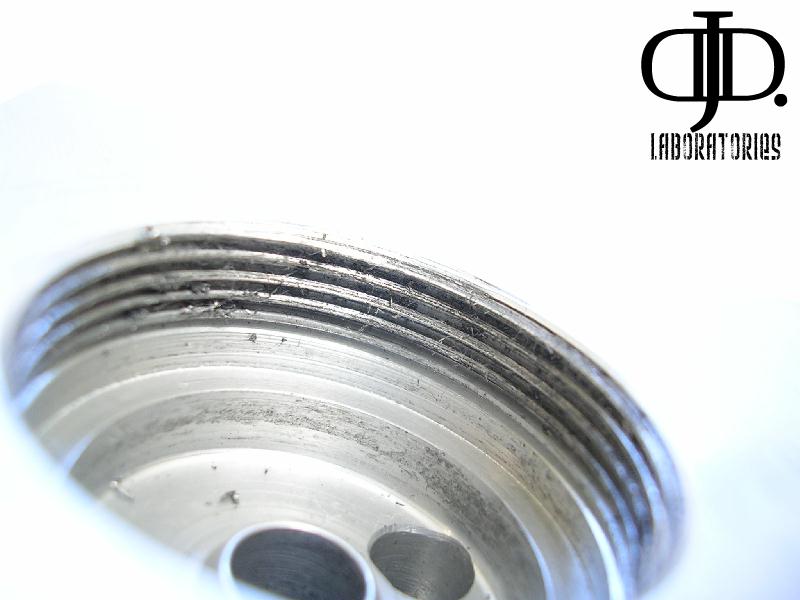
One of these is the machining quality. The threads on the bag ports where nicked along the threads and had metal shavings left inside. (This picture was taken of a port between valve segments) so I know it was not used for testing.
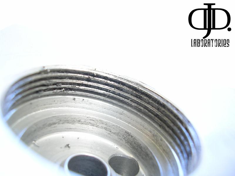
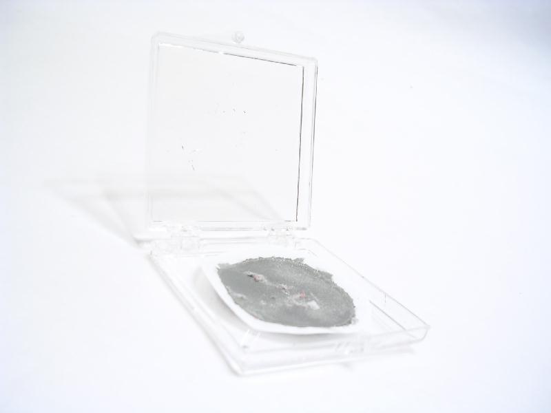
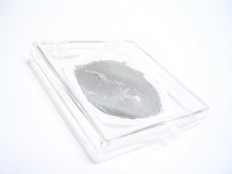
This really bothered me. I had a very hard time removing 3 of the valve stems. After removal I found out why, the threads of the valve block where marred with allot of metal shavings internal still on the threads. Any of these shavings could get into parts of the valve and damage its seals
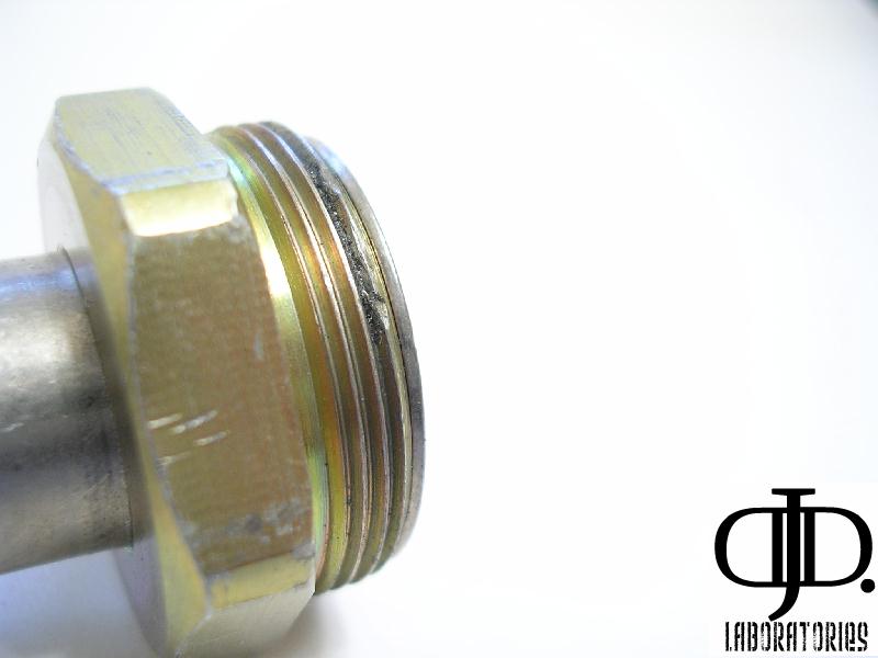
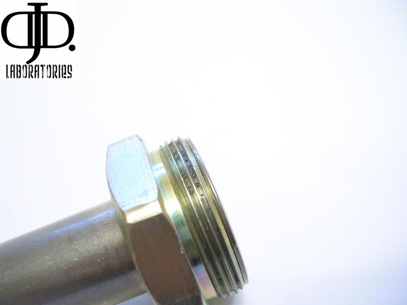
As you can see the threads of the valve stem where damaged during production and when installed into the aluminum valve body destroyed the threads and created metal shavings.
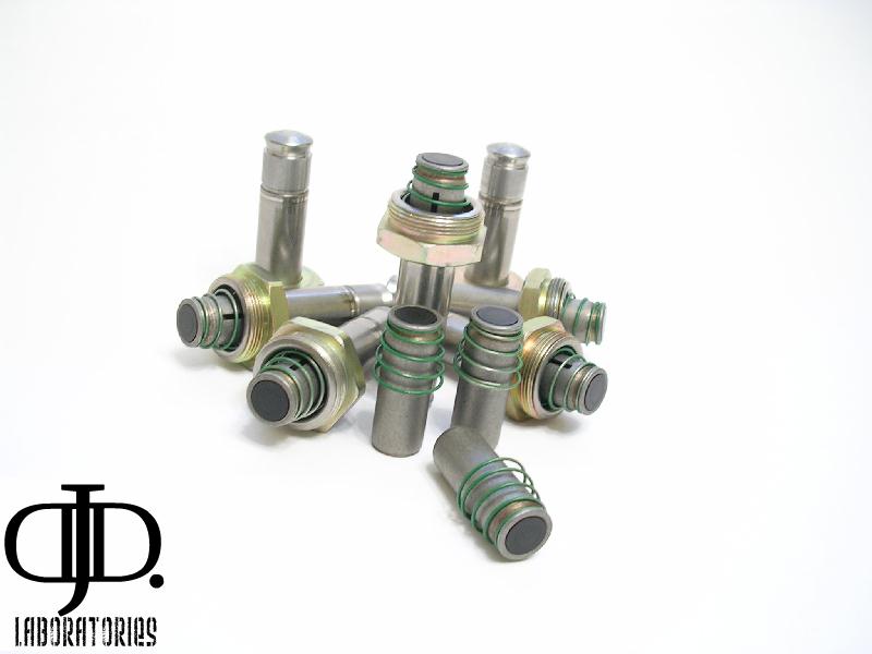
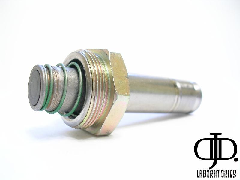
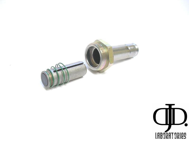
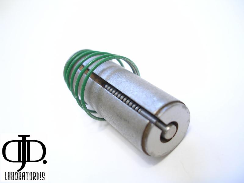
Here is one feature I have yet to see in any valve design.
Inside you will see a spring pin. What this pin does is slow the acceleration of the core as it flies open and pounds into the upper valve stem. This will help prolong the valve and give less of a ‘CLICK’ to the operation. This little spring also will push the core away from the magnetized center after you release power from the coil this will help the valve close a fraction of a second faster. (Nice little touch)
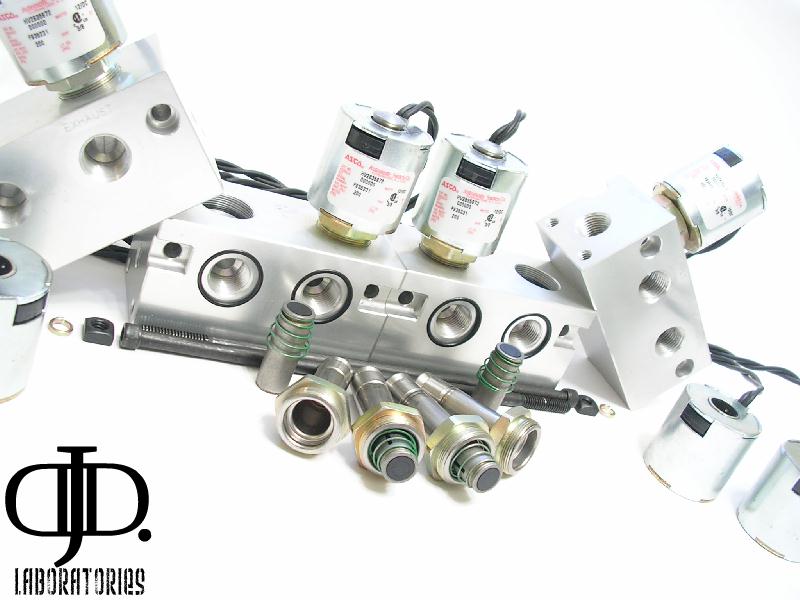
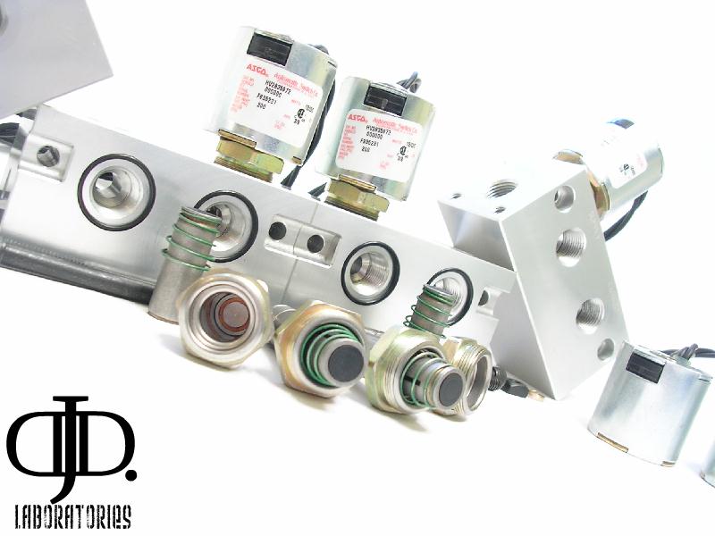
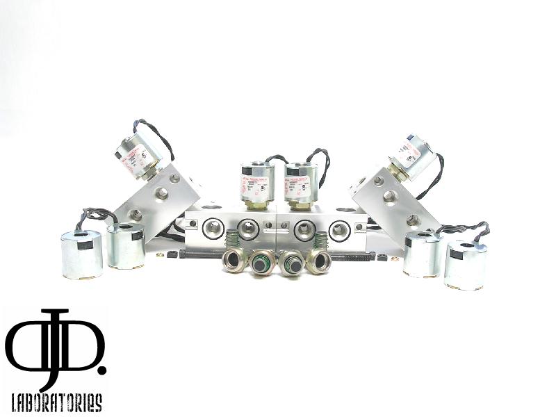
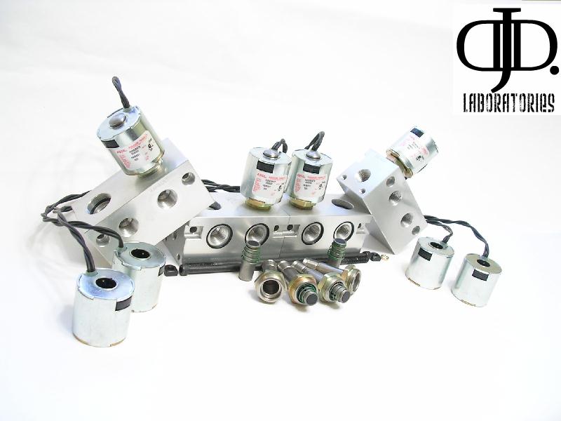
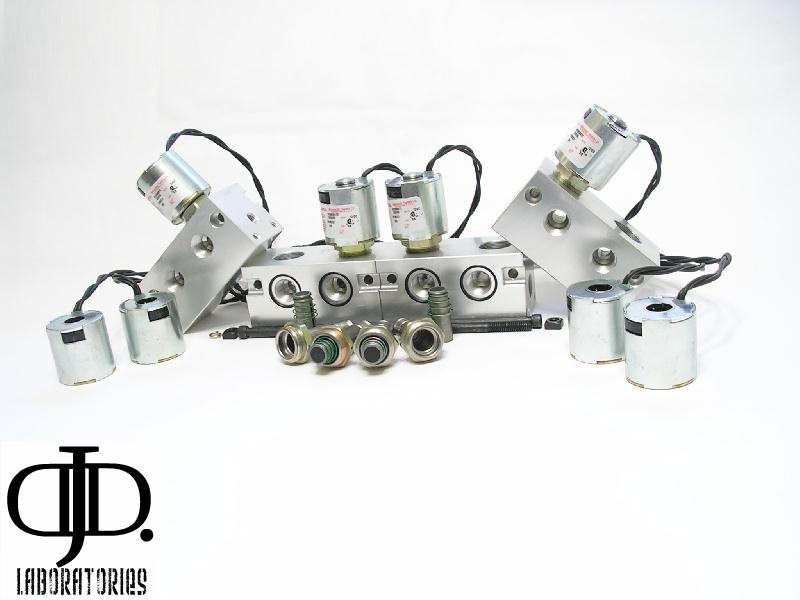
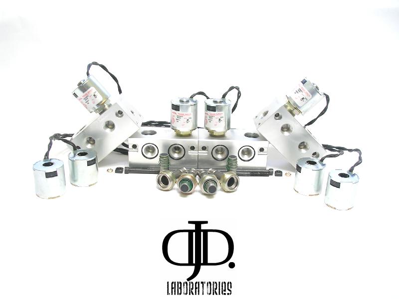
Here are all the parts the pictures do a great job of explaining themselves here.
MS”]
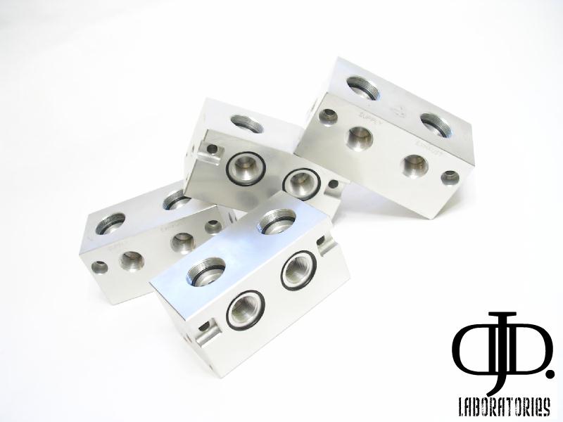
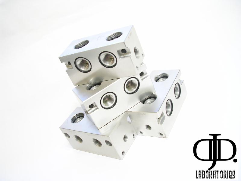
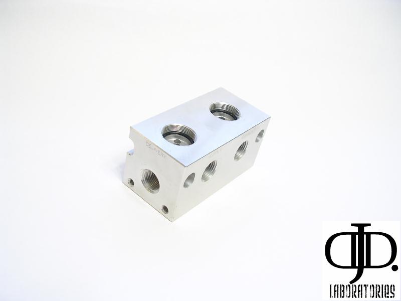
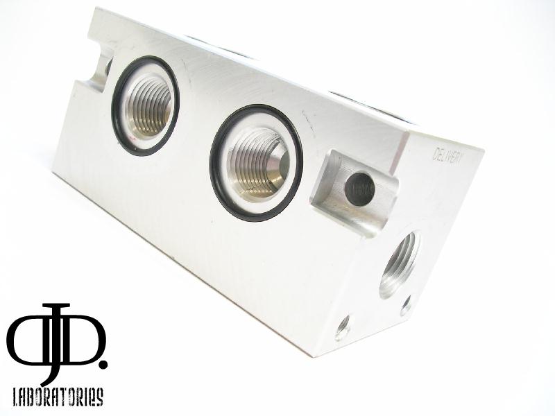
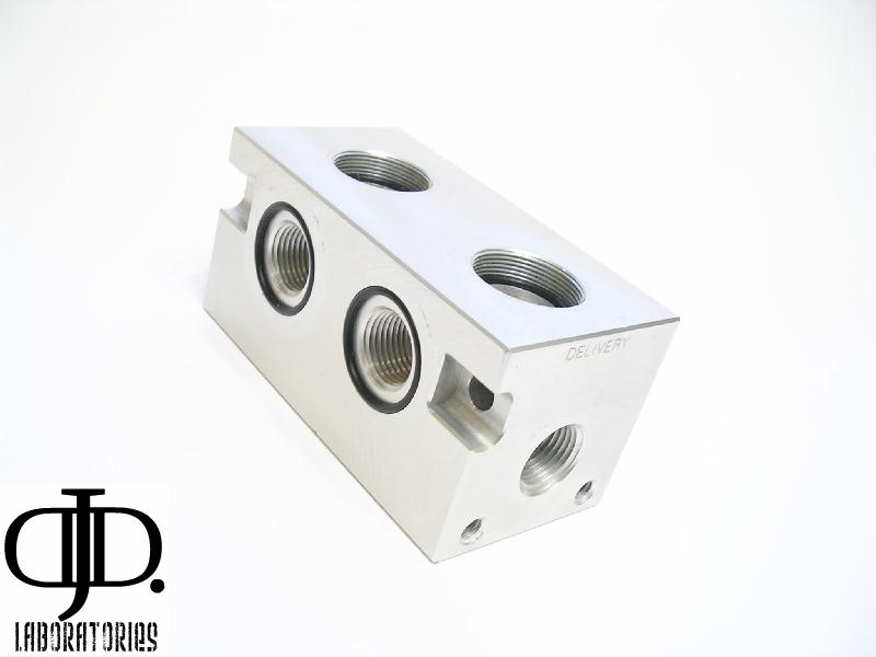
The great part of this valve is the modular sections you are not stuck with its current layout. You have the option to break it apart or even expand you system as you see fit.
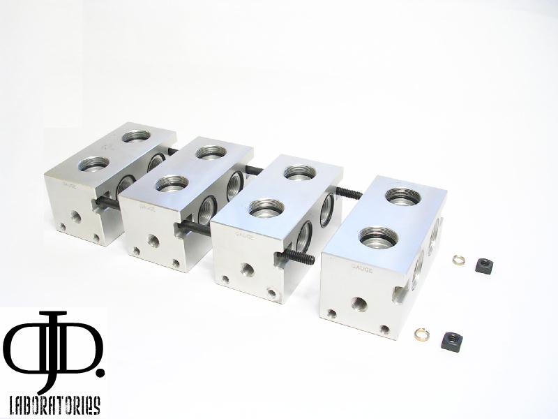
This shows how the valve group is held together. If you where to split it in half (2 blocks each) you would only have to buy 2 new Allen bolts and 2 new square nuts. And you are set. Also this is nice if you have to clean out anything internally stuck in your valve. With it apart you have access to every passage way.
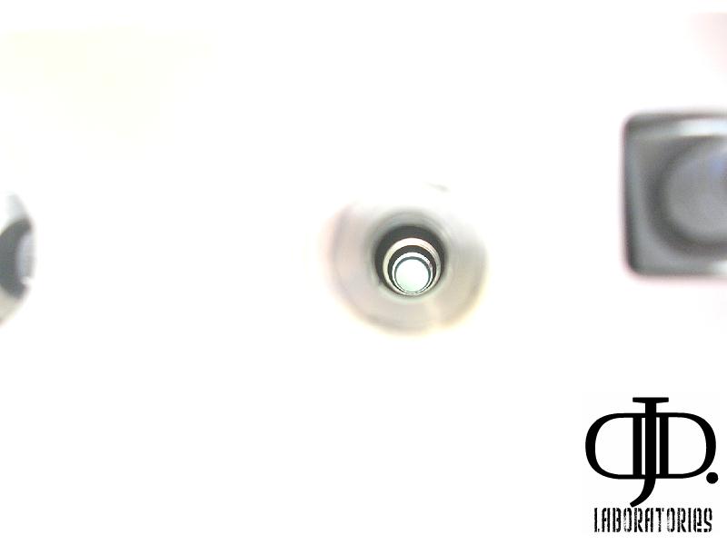
This part has me a little concerned. This picture is looking straight down the 3/8” Feed port. There is so many changes is diameter the air is constantly contacting speeding up then expanding (slowing down) as it passes down the valve body. I can see this turbulence effecting 4 corner lift speeds.
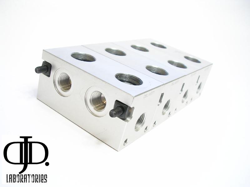
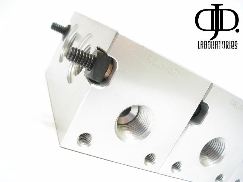
This part of the valve bothered me some ( I understand bolts only come in certain lengths) but why not cut the bolts and re finish the end with them sticking out the end you risk damage to the threads leading to a hard time disassembling the valve.
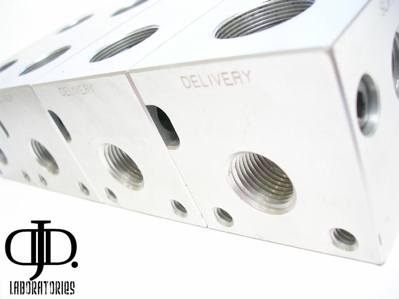
All Ports are clearly etched with there function.
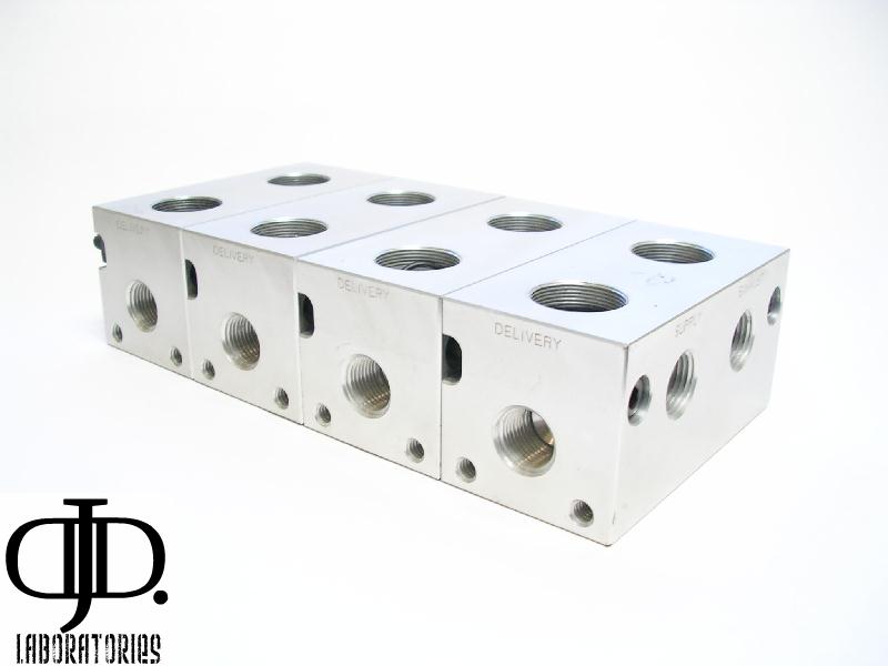
One thing I would like to point out is the mounting options.
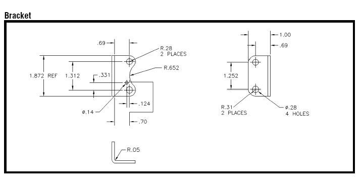
There really are none. The only way to mount this valve is the small holes along the front and back bottom. So some sort of angle bracket would be needed. That would also have to clear your fittings.
All in all this is a really nice valve but due to some functional shortcomings and machining practices I am going to have to rate this valve 7/10 This does not mean it will not work for your needs. It only states there are some issues that may affect your installation life span and or maintenance to the valve.
As always further test results will follow.
If you have any questions please ask.
Here are the pics,
BEFORE,
AFTER,
Ok I did a flow test tonight!
IT is ratted at 0.7Cv
I tested it at 0.848Cv
A lil faster then ratted.
BUT This is directly connected to a 3″ port on a 12 gal tank ![]()
I tested the far coil then the closest coil to the air supply ( no notticeable difference so the limiting factor is the valve orifice) . I also only used one supply port.
keep in mind the Cv is still slower then most 1/4″ valves on the market.
Parker 1/4″ 1/4″ orifice .76Cv
SMC 1/4″ 10mm orifice 2.0Cv
Also a nice loud PSSST sound though ![]()
The valve operates very solid. Nice crisp on and off.
