This page cornicles the massive project I took on, of bringing an old Adept SCARA robot back to life by building my own controller front end for it from scratch using Arduinos.
Here is a Video introduction to the project,
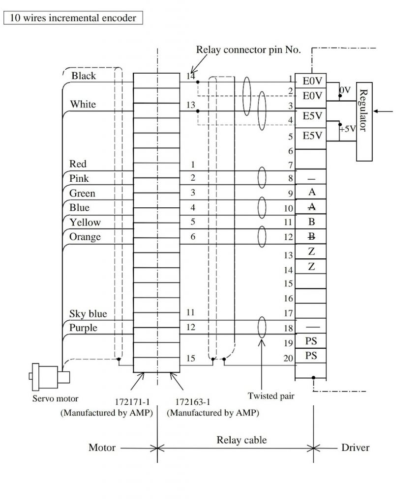
Next step was to see if I could interface with the encoders, and get data from them. This was a process!
Found some information online, that helped figure out why there where so many wires on the encoders!
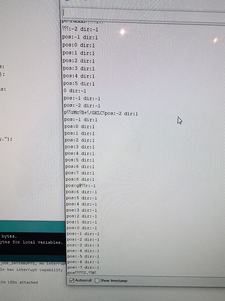
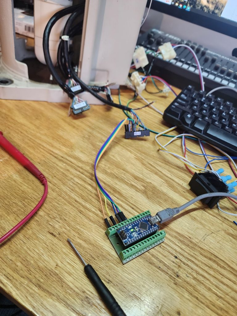
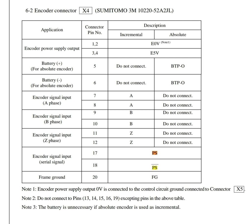
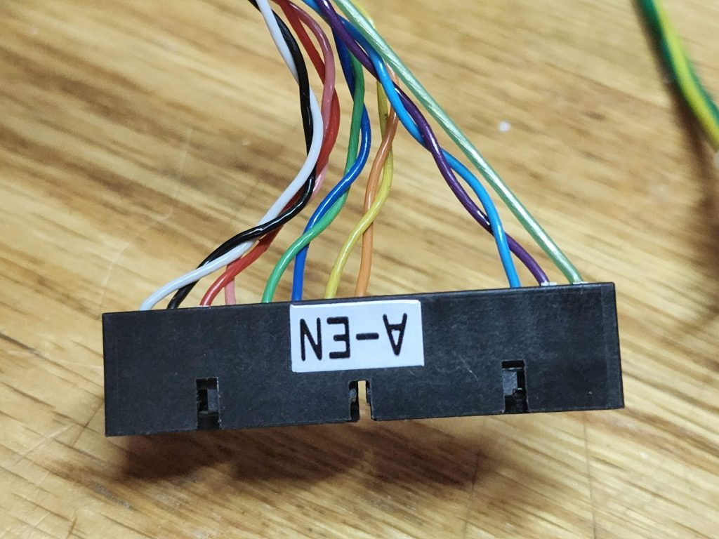
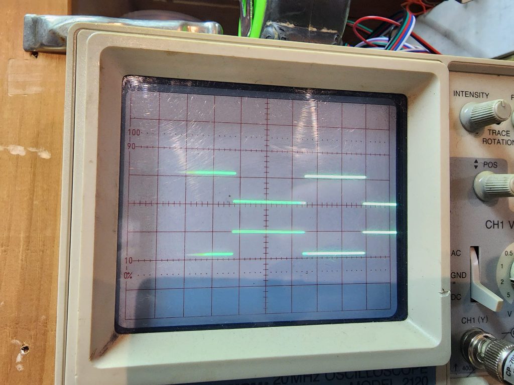
Now lets see if I can read data in real time!
This is Awesome! Now that I know where it is.. I need to be able to move it! .. but this time with a controller..
This was very much a project, reverse engineering the old robot motor drivers, to figure out how they used to work, and how I can make them work with an Arduino. This robot is a bit off, the encoder does not connect to the drives in any way the PC was used to read the data, and do the PID loop and sent data to the drives. Data is a loose term, it sent pulses via differential pairs to the control drivers. Not much smarts in these drivers. Old logic was just not fast enough like it is today!
Once I was able to drive a large 3Phase motor and fine tune my code, it was time to test some robot movement with direct and speed control!
How exciting! Now I need to combine the encoder code, with the motor code, and close the loop!
It is starting to feel like a proper robot now! Now that I know I can read and control one axis, I need to close up all the parts I have hanging out, and clean up the mess, it is time for production!
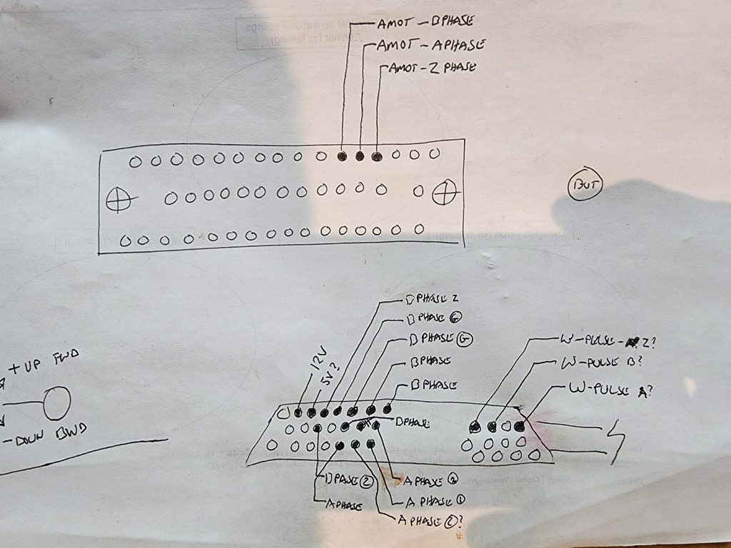
Reassembled the controller and I am now using all original cables! Spent time pinning out the arm signal cable, still have a few mysteries, like the home position sensors. I do know they are NPN so should be easy to find what pin with some power. Need to wire up 4 more Arduinos now…
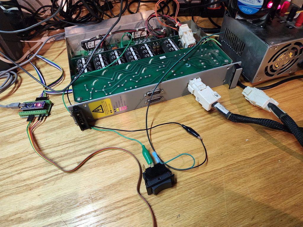
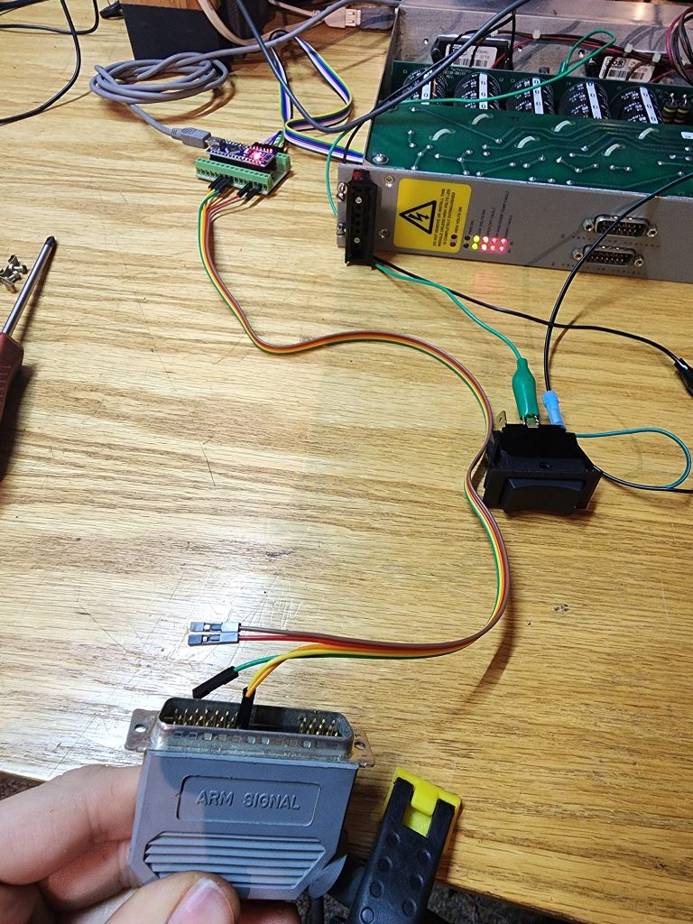
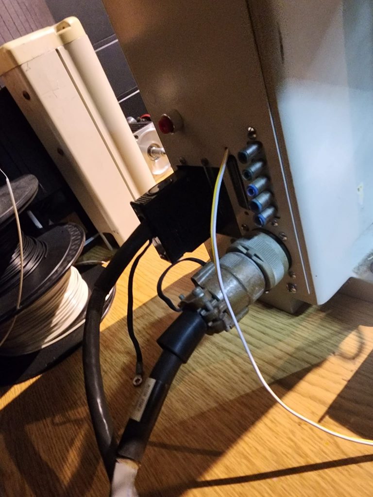
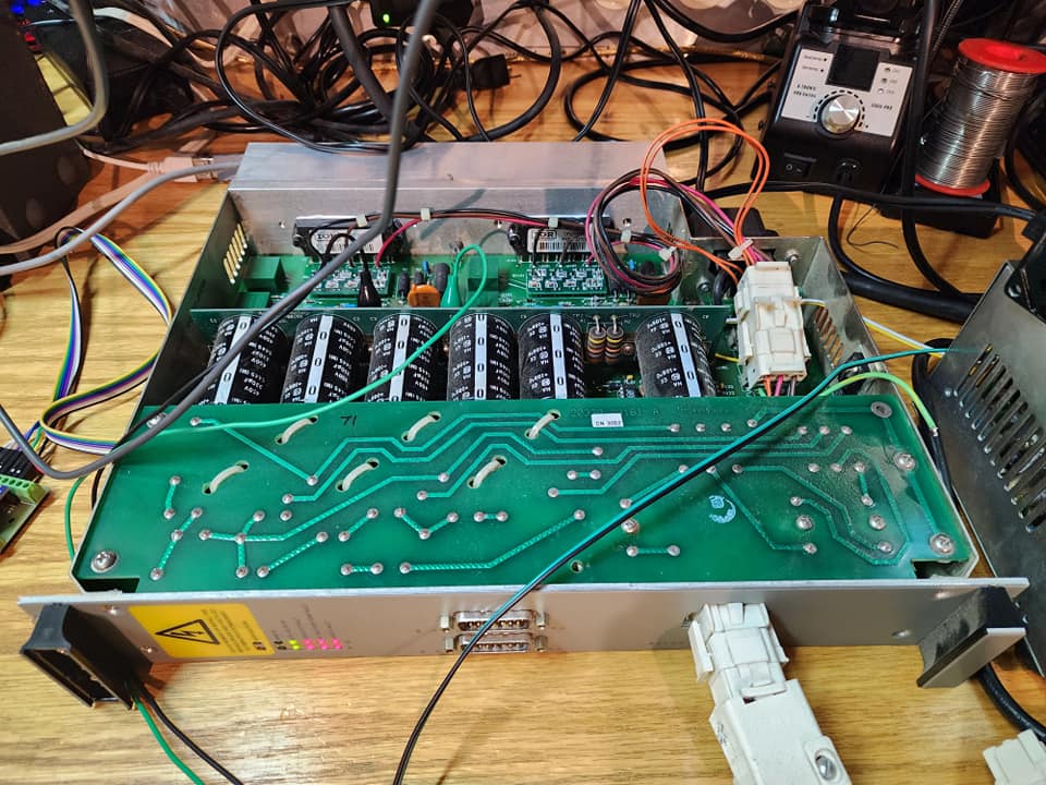
Check out the OG controller for it!
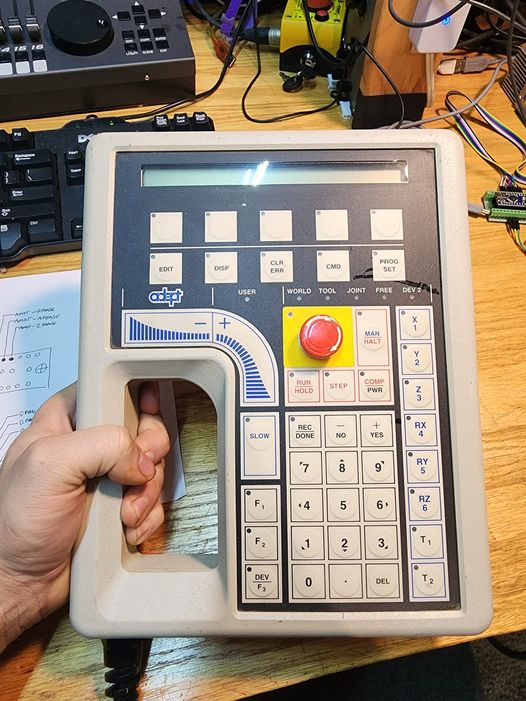
After some more late nights I now have Position control with random targets and ramp down.
My struggle of using old gear to build this robot controller did not go un-noticed. I received this awesome donation to the lab! A digital Oscilloscope, what a difference a few decades makes! this should make prototyping the waveforms of the controller so much better! Huge thanks the the person who donated this, you know who you are and how amazing this is to me!
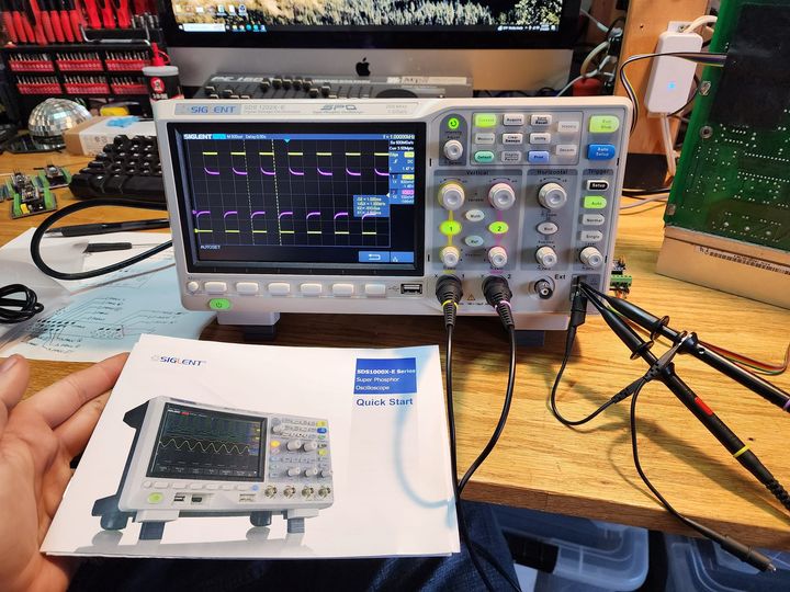
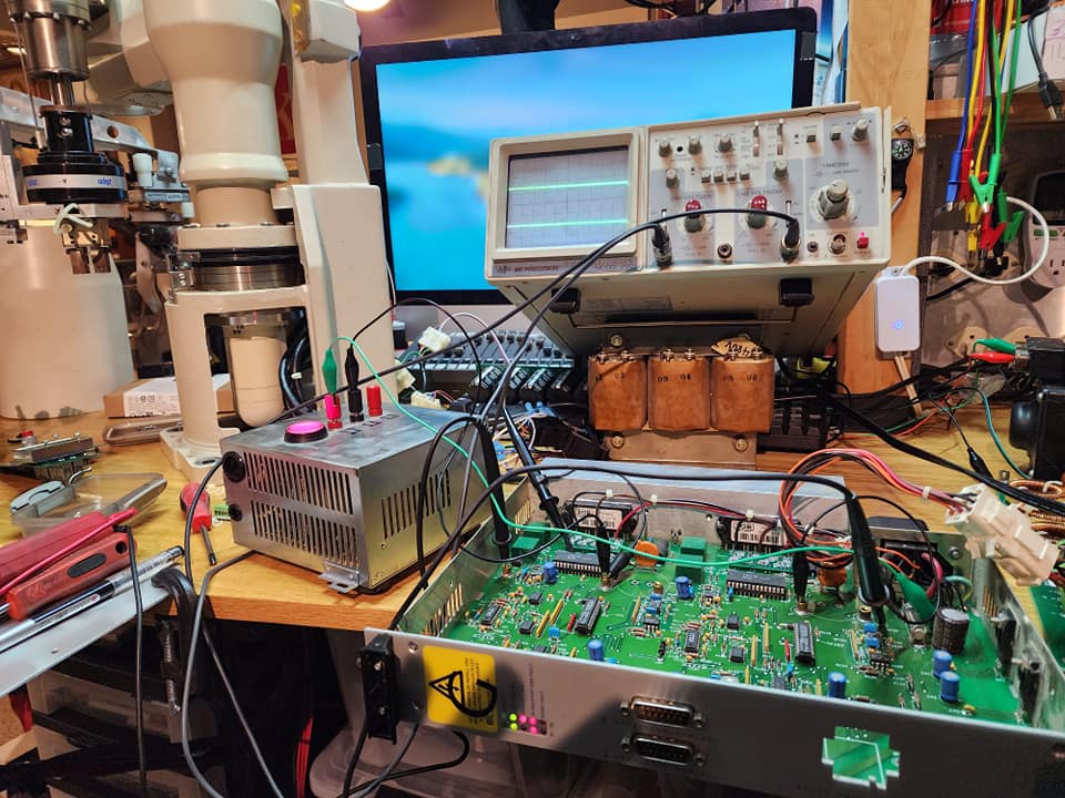
I asked Chat-GPT to help generate code that would control one axis of my robot. I fed it exactly what I am doing now, to see how it would do it… and this is the response I got…
“The code for this project will likely be complex and require a significant amount of programming expertise. It may also require external libraries and components, depending on the specific components and interfaces you are using. You may want to consider breaking down the project into smaller, more manageable parts and building and testing each component separately before integrating them into a single project.
I hope this information is helpful, and I wish you the best of luck with your project.”
Wow even Skynet thought this was complex and wished me luck hahahah .. oh welll.. back to hammering this out myself lol.
Generating mimicked sinusoidal 3phase variable frequency output with one half of positive sine on one pin and other negative half of sine on other pin apparently is not easy ![]()
I now Have speed ramping in both directions! The new scope was paramount in helping debug this process.
Now lets see if we can do 3 axis at once!
Next step was to build a front end, that would let me send data to the robot, the problem was it has 4 Arduinos, how do I do that? I use I2C communication, and a master Arduino, the master connection via USB/serial to the PC, terminal window, it takes the data, and depending on the letter will send just that number to the Arduino that runs that axis.
Wow, taking a stab in the dark and being nice, can pay off! I reached out to Omron, formally Adept and said, I have an old 550 unit, that was obsolete 20 years ago, I am building my own controller for it, and would you be able to help me out and verify my pinout I reverse engineered, and help with a few I am missing.
I got this cool old guy, who went around and grabbed every internal document they had on the 550 and sent it to me! It has every schematic, every layout, and even the training manual for the internal techs that explains the theory of operation, not just how it all works but why. This has been an amazing read, and man was I close! These documents are going to be amazing as I go on with this!
Sometimes, just being nice and showing some proof you know what you are doing, goes a long way!
That and they still had documents from a 30 year old robot!
The photos I made intentionally small, for I do not think they are for public release by me! but wanted to show just how awesome they are!
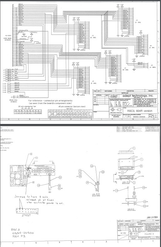
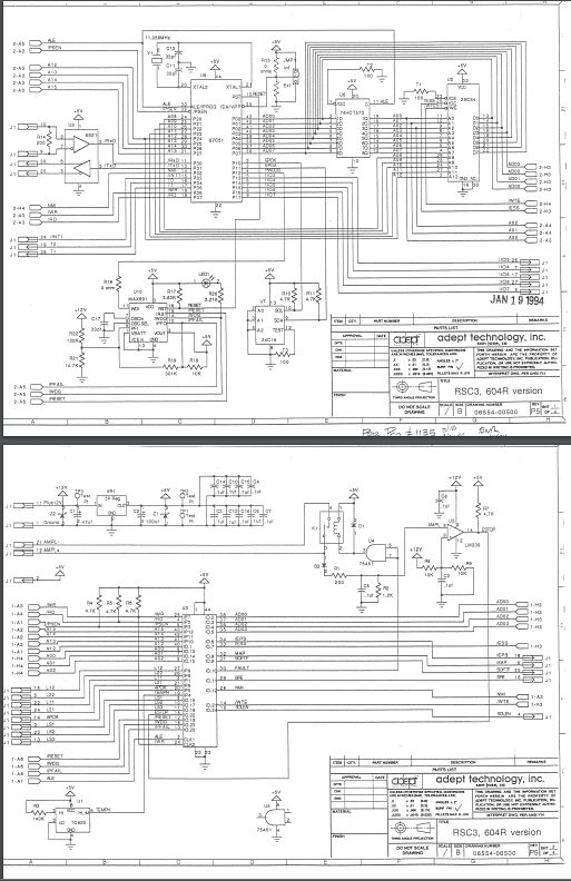
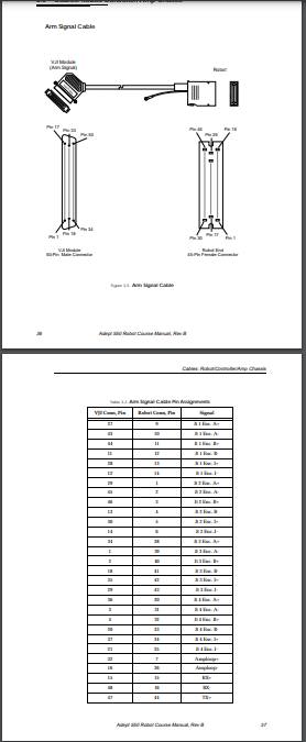
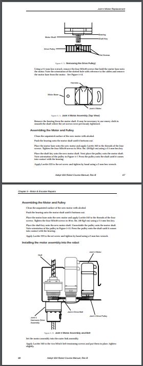
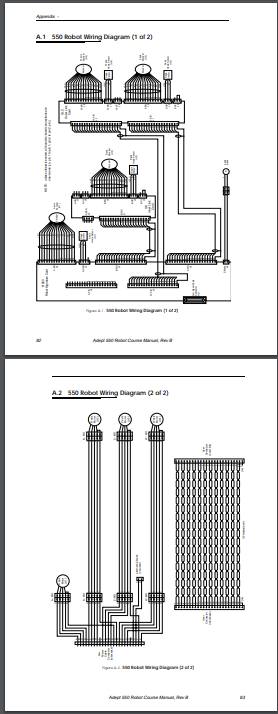
Next step with this new mass amount of data was to figure out the home sensors, that is why I reached out to Adept, turns out they sort of on the data cable, the home sensors are digital 1/0 readouts, that go to a chip in the arm base that converts it to a RS485 data string of all the sensors, this was cumbersome and complicated for my means, so I made up a new cable for just the home sensors that Arduino could understand, and each Arduino axis got its own sensor line to monitor.
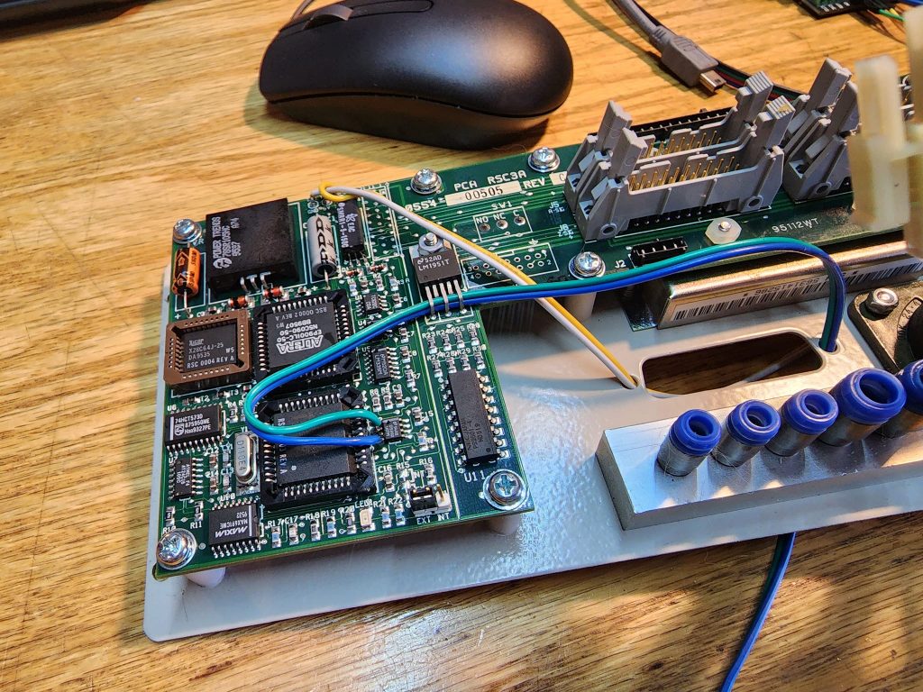
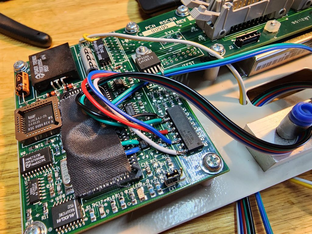
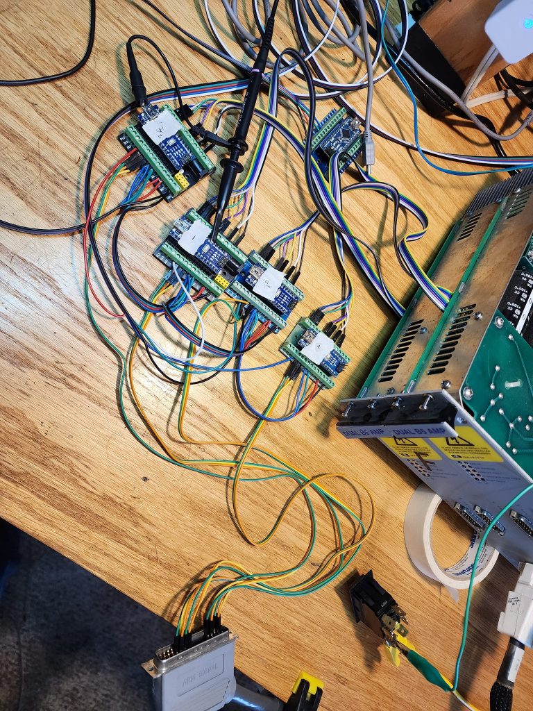
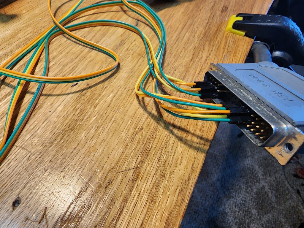
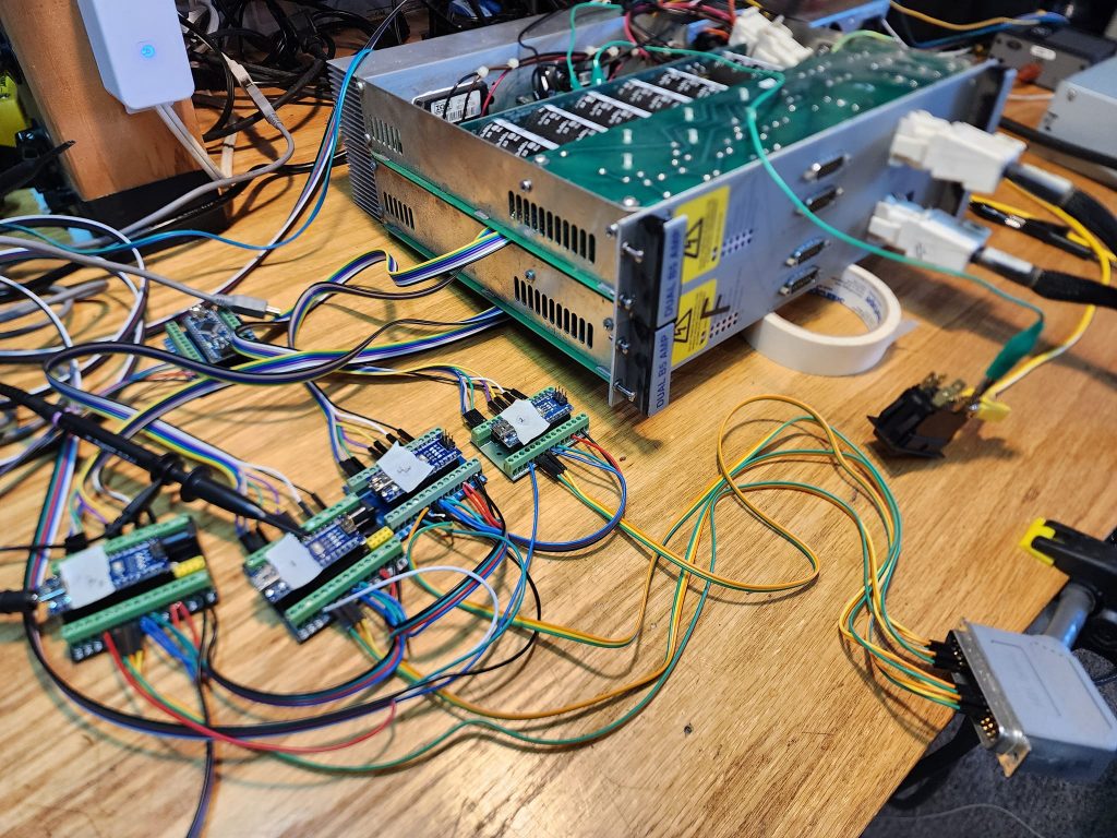
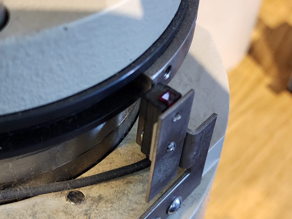
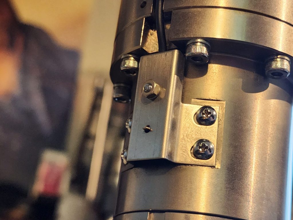
Now that I can sense home, it is time to try out some code! From the manuals I got I learned once it goes to the home sensor it stops. And rotates the motor very slowly until it finds the z phase zero indicator for single revolution That way every time the robot starts it is within one micron of the same position! And eliminates hysteresis errors from the sensor. Neat!
Next fun step will be to read and adsorb this information to build a proper motion platform for it!
Next big hurdle, was to be able to send large 32 bit numbers across serial and I2C to the Arduino’s, for I need massive numbers to maintain proper robot resolution. this involved braking the number down into multiple 8 bit numbers sending them in series and recombining them on the other end!
Here is a full tech walkthrough of the entire project up to this point to show what all is going on, it will help make sense of everything.
Next logical step was to may a Graphical User Interface ( GUI ) to make it simpler to interface with it.
Now that I have an interface, it is time to write the first program for it!
I figured it was most fitting after a decade of sitting and with one foot in the scrap bin in the sky, to bring it back to where it all started in 1996. Here is a photo of how it was left to sit before going to the scrap yard when I saved it. Note the massive silver box under the table, this was the original controller that I replaced with a few Arduinos.
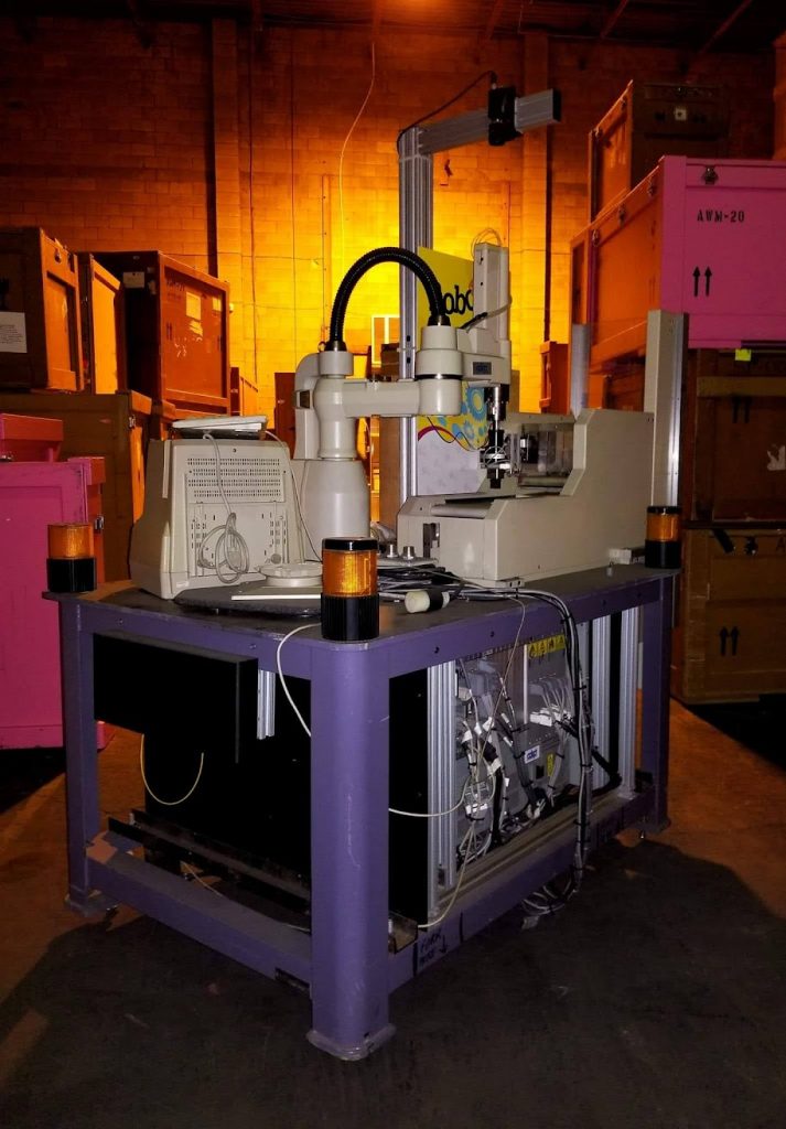
Thanks for taking the time to follow along with this odd but interesting project, if you have any questions or want to know more, leave a comment below! If only to make some suggestions on what you would like this arm to do!
UPDATE: July 2024:
I have made much progress on this project, it now runs on Linux CNC, much more to update here but for now, some quick videos having fun with it!
Maped to a pointer to mark a pattern onto a pumpkin for carving!
And for fun, teaching it a pattern to do polishing of a surface for working on my restoration projects!
Much more to come soon!
Truly Amazing work and ingenuity!
Congrats!