I consider it a great recourse to learn how and why our valves do what they do!
some of the information below is pulled from JAKSA Solenoid Valves
1. SOLENOID VALVE ASSEMBLY AND TERMINOLOGY
—————————————————————————————–
DIRECT ACTING VALVE
This type of valve is normally found in manifold style setups,
example of such are as follows,
Accu Air
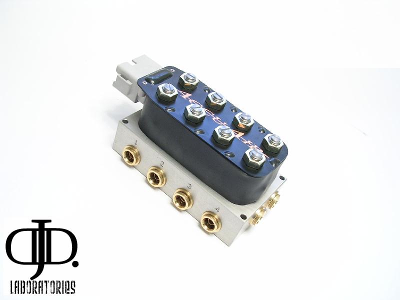
http://www.s10forum.com/forum/f125/new-accu-air-valve-facts-info-288011/
ASCO
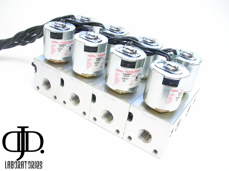
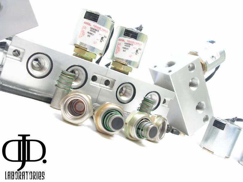
http://www.s10forum.com/forum/f125/asco-manifold-valve-facts-info-290044/
Air Ride Technologies
SMC
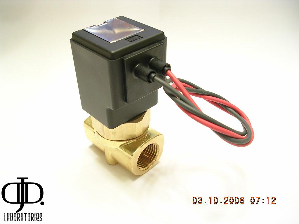
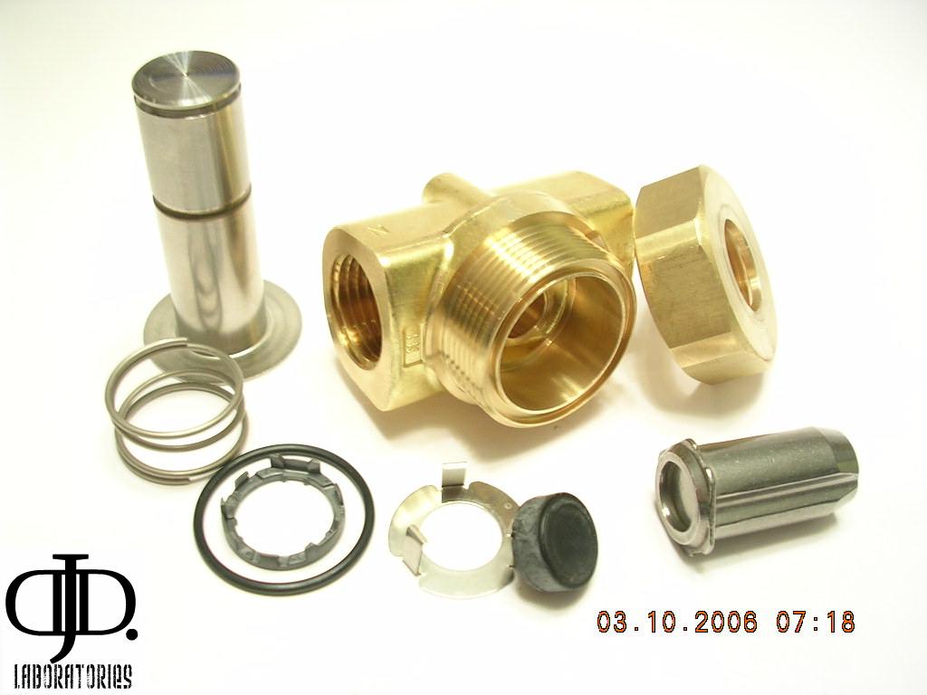
http://www.s10forum.com/forum/f125/smc-high-pressure-valves-facts-info-237362/
As well is they come in many other forms.
1. Solenoid coil
2. Solenoid base (or shaft)
3. Core
4. Spring
5. Disc seal
6. Valve body
——————————————————————————————
DIAPHRAGM OR PISTON VALVE
This Valve design by far is the most common for our use.
Some examples are as follows,
AIRLIFT
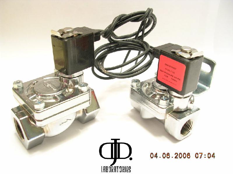
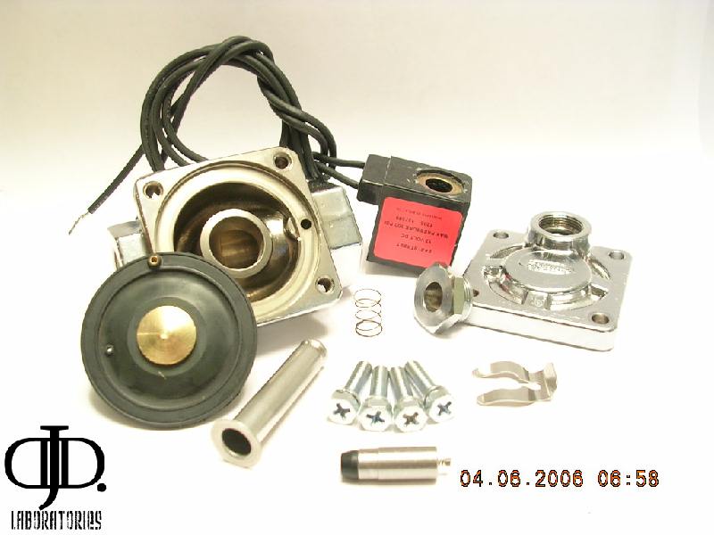
http://www.s10forum.com/forum/f125/airlift-valves-facts-info-242943/
ASCO
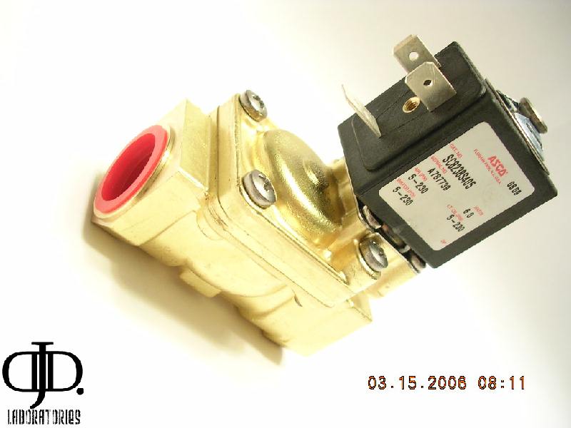
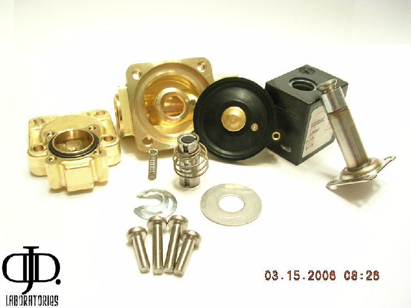
http://www.s10forum.com/forum/f125/asco-valves-facts-info-238454/
SMC 1/2″
http://www.s10forum.com/forum/f125/smc-valve-cleaning-how-237585/
These valves come in almost every size.
Even massive 2″
1. Solenoid coil
2. Solenoid base (or shaft)
3. Core
4. Spring
5. Disc seal
6. Valve body
7. Diaphragm or piston
8. Diaphragm (or piston) spring
9. Bleed (or pilot) orifice
10. Valve bonnet
PISTON VALVE
This valve is not to common it will function the exact same as the DIAPHRAGM valve above only difference is a metal piston is used in place of the rubber diaphragm.
An example of this type valve we use is made by DANZ
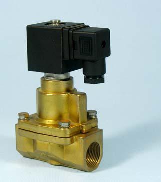
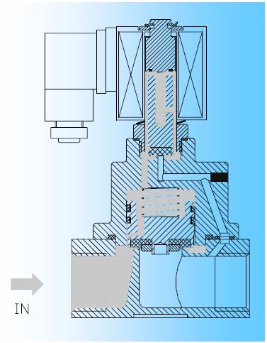
Again this style comes in many shapes.
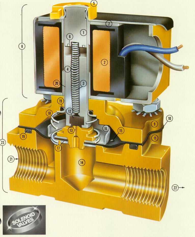
UNIT SOLENOID
1. Pole Piece
2. Coil
3. Spring
4. Plunger
6. Shading Ring
7. Magnetic Frame Assembly
8. Unit Solenoid UNIT VALVE
5. Gold Ring
9. Bonnet
10. Diaphragm
11. Valve Body
12. Disc
13. Pilot Orifice
14. Main Orifice
15. Bleed Orifice
16. Diaphragm Cup
17. Diaphragm Support Washer
18. Diaphragm Return Assist Spring
19. O-ring Seal
20. Plunger Tube
21. Inlet
22. Outlet
23. Unit Valve
Principle of operation combines direct acting and pilot. Valve diaphragm or piston is attached to the solenoid core and no pressure difference is required. This principle allows high flow rate at pressure near 0 bar.
4. ELECTRICAL CHARACTERISTICS
All solenoids are designed for coninuous duty (ED100%). Exceptions are marked on individual solenoid or valve types.
Wire inulation is class F (155°C) or H (180 or 200°C).
Voltage tolerance is +/- 10% at AC and +/- 5% at DC.
Power consumption is stated in watts (W) and equals:
– the product of measured DC voltage and current
– the product of measured AC voltage and current multiplied by 0.6
Thermal conditions
After the solenoid has been energized for a period of time the temperature of the winding rises. Amount of heating is affected by ambient and fluid temperature. In extreme cases the overheating causes damage to the wire insulation and the solenoid becomes defective. Special solenoids for extreme thermal conditions are also available.
Electrical protection – IP rating
Apart from standard solenoids, original explosion- and waterproof types are also available, thus allowing the use of solenoid valves in practically any environment. Standard solenoids are encapsulated in special thermoplastic resin which prevents the intrusion of damp and protects the winding from mechanical damage.
Explosionproof solenoids are encapsulated in epoxy resin. Basic IP rating for a solenoid is IP00, whereas IP65 can be achieved with properly fitted plug (to DIN 43650).
TM35k type solenoid with IP67 rating is designed for extremely damp ambientes (also water immersion).
5. FLOW RATE AND Kv VALUE
Flow rate of any given valve depends on valve size, type of fluid and the pressure which forces the fluid through the valve. Kv value is given for each valve type in the table. With known parameters the flow rate can be calculated according to the following formula:


Q……flow rate [l/min]
Kv…..value given in the table for each valve type
p….difference between inlet and outlet pressure [bar]
p1…..pressure measured at valve inlet [bar]
p2…..pressure measured at valve outlet [bar]
……specific mass of fluid [kg/dm3] (equals 1 for tap water)
Kv value is approximately the same for tap water and other fluids (e.g. oil) of viscosity not exceeding 21mm2/s. At higher viscosity a correction of Kv value is required.
1 CFM = 28.328 l / min
Kv=L/m
Example 1/2″ Pilot operated diaphragm is 20KV at Water 1bar or 14.7PSI
The flow coefficient – Cv – and the flow factor – Kv – are commonly used to specify the capacit of control valves.
The Flow Coefficient – Cv
It is often convenient to express the capacities and flow characteristics of control valves in terms of the
* Flow Coefficient – Cv
The flow coefficient – Cv – is based on the imperial units system and is defined as:
* the flow of water through a valve at 60 oF in US gallon/minute at a pressure drop of 1 lb/in2
The flow coefficient is commonly used in the U.S.
The Flow Factor – Kv
The metric equivalent of the flow coefficient – Cv – is based on the SI-system and is called the
* Flow Factor – Kv
The flow factor is defined as
* the flow of water through a valve at 20 oC in cubic meters per hour with a pressure drop of 1 kg/cm2 (1 bar)
The flow factor is commonly used outside U.S.
Converting between Flow Coefficient Cv and Flow Factor Kv
The connection between Cv and Kv can be expressed as:
* Cv = 1.16 Kv (1)
* Kv = 0.853 Cv (2)
———————————————————————————————-
6. PRESSURE RATING
a) Maximum operating pressure differential is the maximum difference between valve inlet and outlet pressures at which the valve will still reliably operate. Values in tables (with tolerance +/- 10%) are given at ambient and coil temperature 22°C.
b) Minimum operating pressure differential is the minimum difference between valve inlet and outlet pressures at which the valve will still reliably OPEN. If required pressure difference is not achieved the valve will not open when activated.
For example a 3/8″ SMC valve will not open at 250PSI because the differential of pressure is greater then the 200 It is ratted for. It simply takes more power to open then the coil can supply so your valve is now ‘stuck’
c) Maximum static pressure is the highest fluid pressure endured by valve body and internal parts without damage.
I find if you exceed this value the valve plate (weakest point) will flex and pass air around the seal and worst case deform or even explode violently.
7. INSTALLATION AND RECOMMENDATIONS
Solenoid valves can be installed horizontally or vertically. Upright coil position is recommended to avoid accumulation of impurities in pilot which may result in faulty operation. Before installation it is highly recommended to clean the pipeline to minimize the amount of impurities in fluid.
Also keep in mind water runs down hill so if you have any moisture in your tank/lines it will settle in the lowest point in your valve this is very important if you live in an area that is prone to freezing conditions.
—————————————————————————
VALVE PROBLEMS
We have all had or heard of a valve failing at the worst time.
Now that you know how the internals work in these valves you are now a better user of them!
When a valve fails 90% of time it has to do in part with the environment it is placed into.
– Direct Acting valve problems
Most direct acting valves have few if any problems for the fact they have the fewest moving parts and the least number of passages. If you have a problem with one of these valves not working correctly it is most often something not allowing the plunger to seal tight against its seat. Simple pull the valve apart and clean off the seal surface and seat. The only other problem is if contaminates have got into the upper shaft and plunger area this will keep the plunger from opening fully closing slowly or in worst case freezing the plunger it whatever position it was last in. Simply disassemble the valve and remove the plunger and clean out the internals with compressed air or isopropyl alcohol. If the plunger is stuck DO Not pry or pick it loose simply hold it in one hand and pound your hand (not the valve part) against something or your other hand as to nock the plunger free of the shaft tube. If you need to re lubricate the plunger you can use white lithium grease. (be sure to clean off any old lubricant.
– Remote Pilot operated
These valve seem to have the most problems associated with them.
For the reason they have the most moving parts of all these valve designs.
If you valve is not sealing correctly or not opining or closing correctly please follow this tutorial,
http://www.s10forum.com/forum/f125/smc-valve-cleaning-how-237585/
These valves by design have many small internal passage ways as well as 2 internal springs and 2 sealing surfaces. Think of them as 2 valves in one package. The problem is small mater such as tank scale Teflon or thread sealer and small particulate get stuck over time in these small passages springs or seals and prevent the valve from operating at there full potential.
Worst case in northern climates these small passages a notorious for ‘freezing’ where water or moisture will freeze solid in these passageways and prevent the valve from operating. If you have to heat the valve the best place to warm it is close to the neck of the valve where the coil meets the body of the valve (where most internal passages are)
– Combination Pilot
These valves seem to be the best of all worlds. They combine the simplicity of a direct acting valve with the high flow of a remote pilot. But they leave out one extra spring and one passage way in the process this means 2 less points of failure. To help find a solution to your problem with this valve you will need to read the guide for both valve types above.
I will keep updating this as I have allot more info to add
