This project started with a friend of mine offering me an old generator he got many years prior and never ran it. The unit has sat in a shed not run for over 30 years we speculate. So I decided to take on the project of bringing this old Onan back to life!
This is my first ever Onan, but I am not new to small engines or heavy equipment. I am learning as much as I can as fast as I can to try and bring thing back from the dead.
Will this be a 100% restoration? No… Will this be all 100% NOS OE Onan parts? Also no… Being that a single small bearing is $140 from Cummins/Onan.. I am not about to dump $1K into a $250 or so valued generator.
Here is what I know so far, it came out of an RV was running at the time the RV was scrapped. so it probably sat in an old RV for some time before being pulled, the unit would spin by hand, so nothing was frozen, it came with a bag of parts.. This tells me someone at some point was trying to figure it out… The side cover for the electrical enclosure is missing completely.
I will spare you the photos of where it was picked up, but think old shed in an old field.. and some sketchy use of physics to get what feels like 400+ lbs of cast iron down a step and onto a trailer by hand.
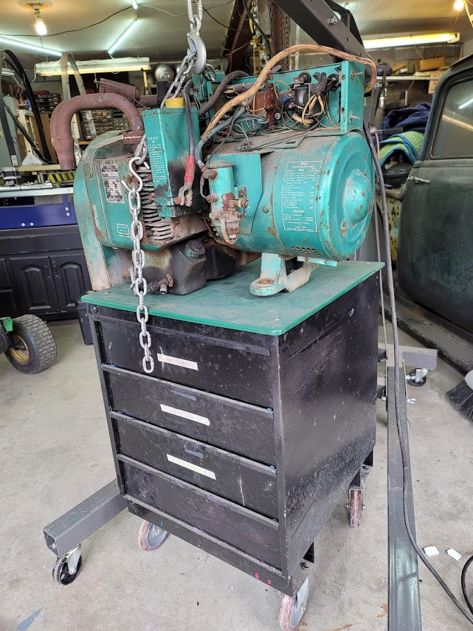
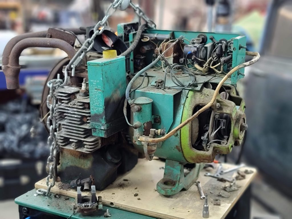
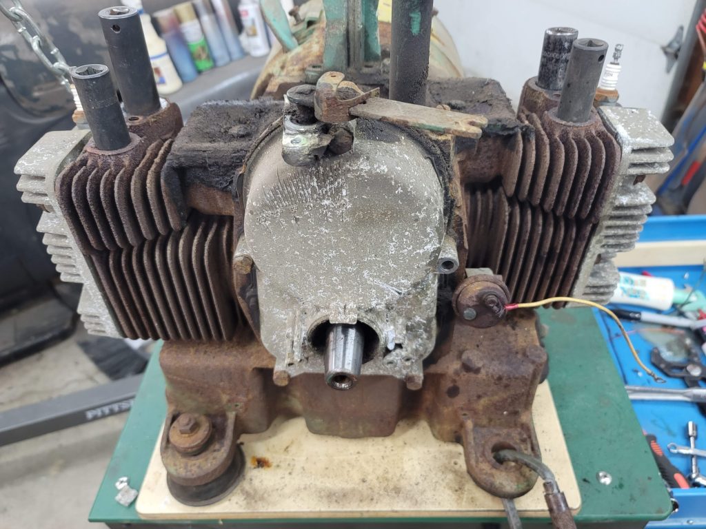
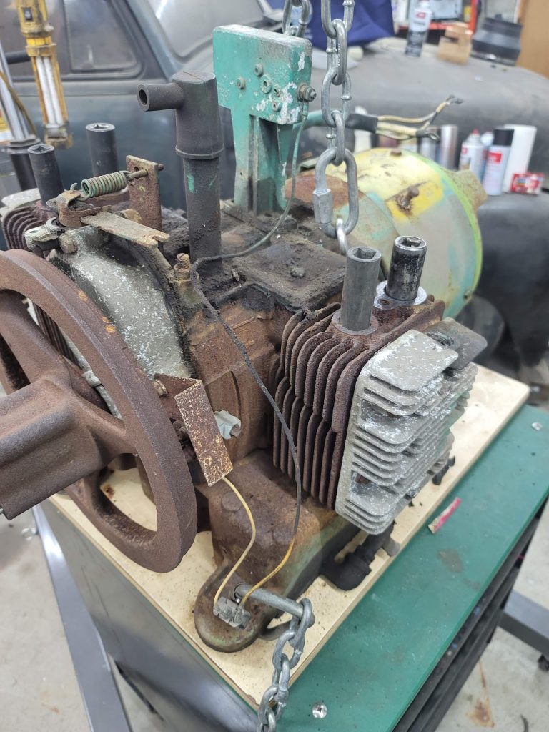
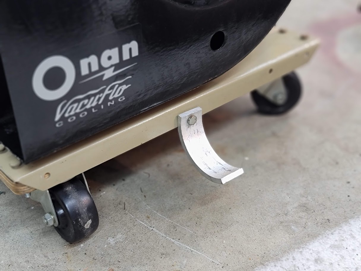
Here it is in all its glory, Just how it came out of the shed. Missing parts and all. I placed it on a tool cart that on paper is ratted for the weight of the unit, but I do not fully trust it, so have the sitting there to catch it in the event of a catastrophic failure.
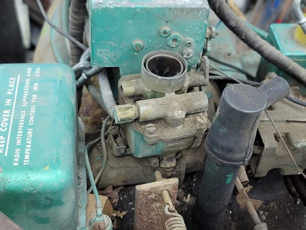
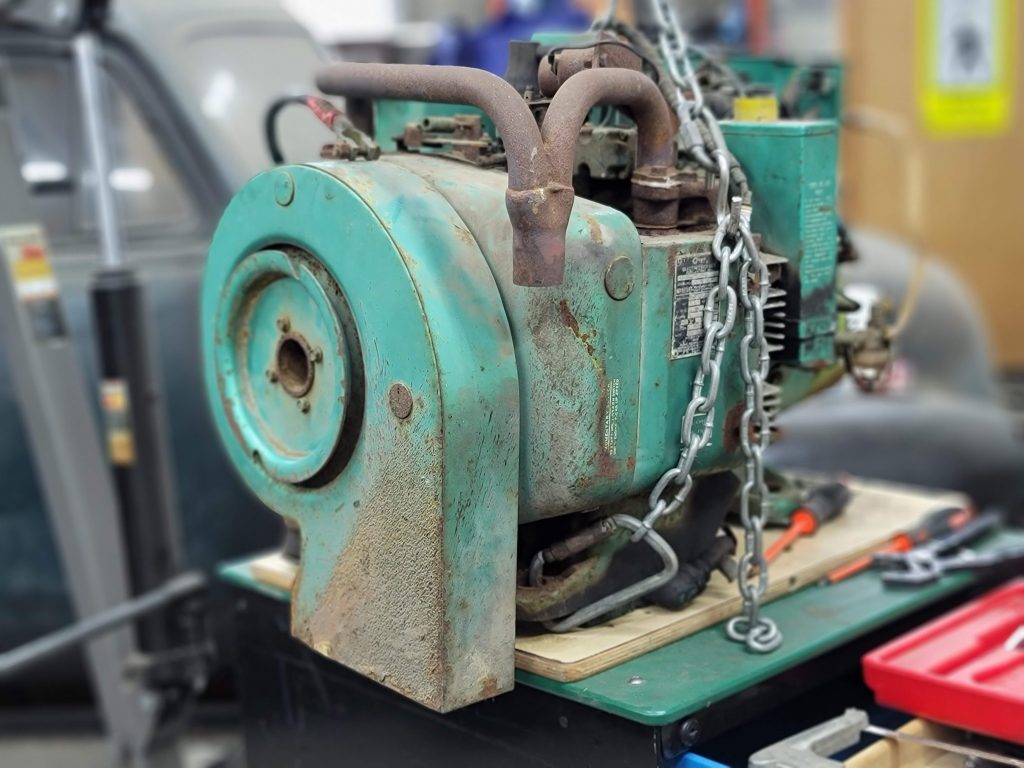
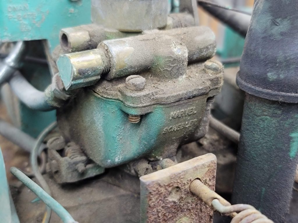
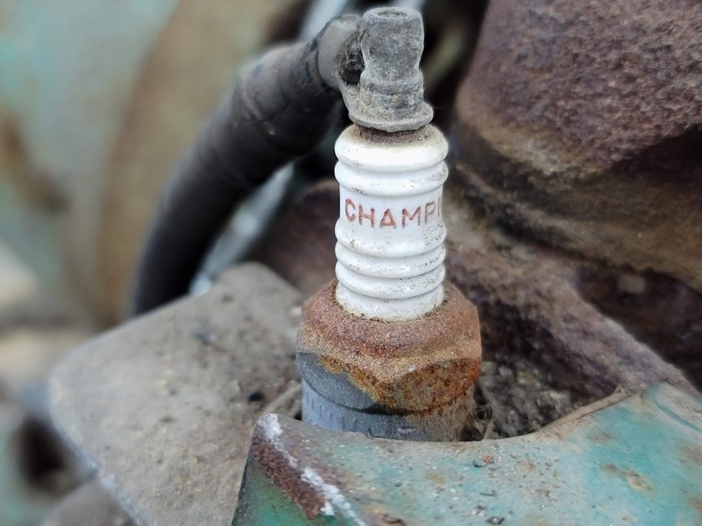
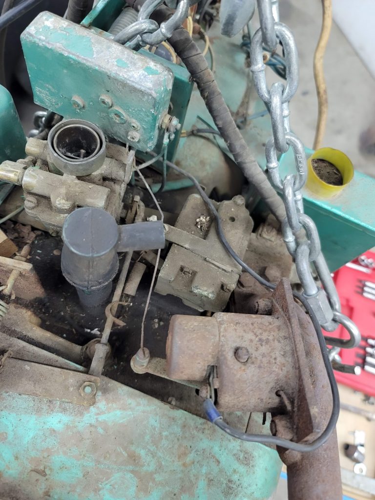
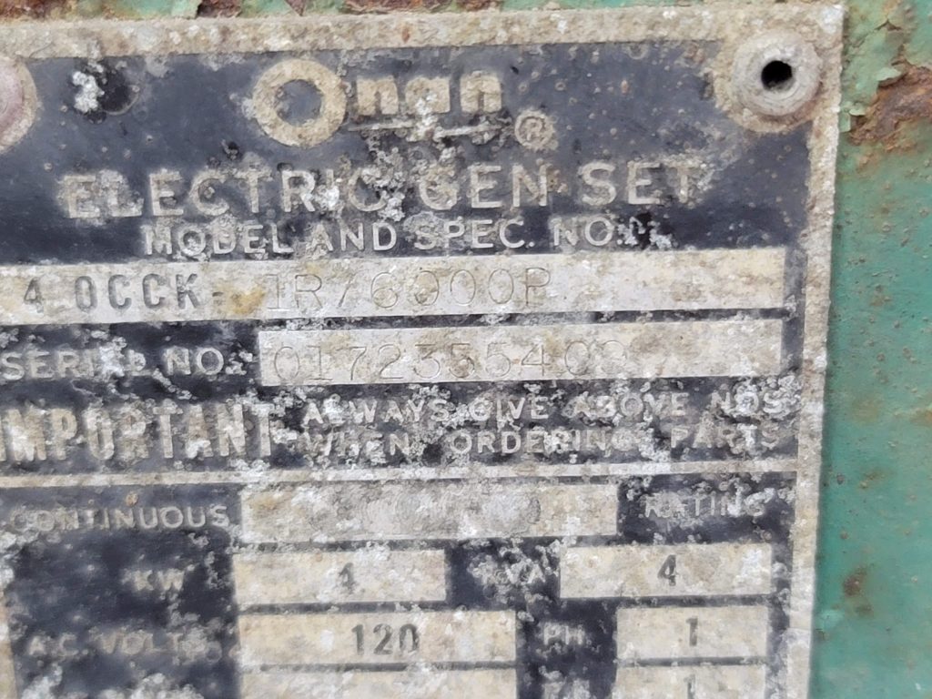
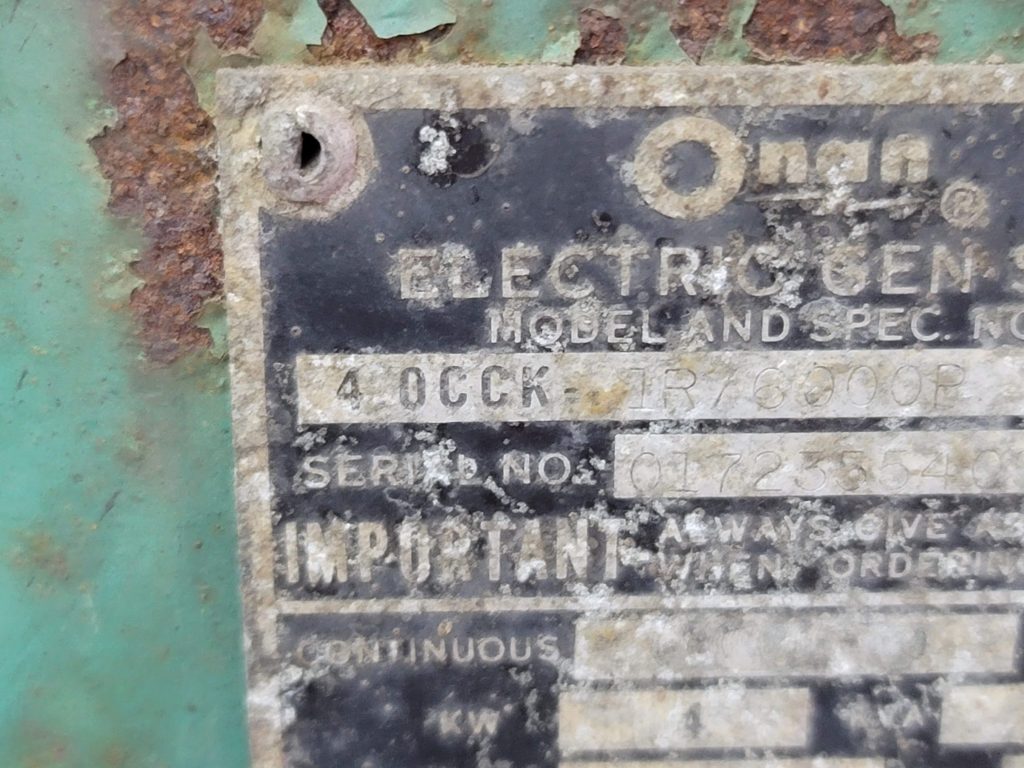
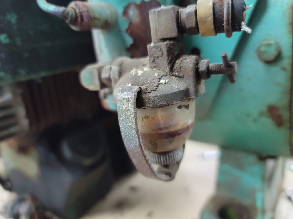
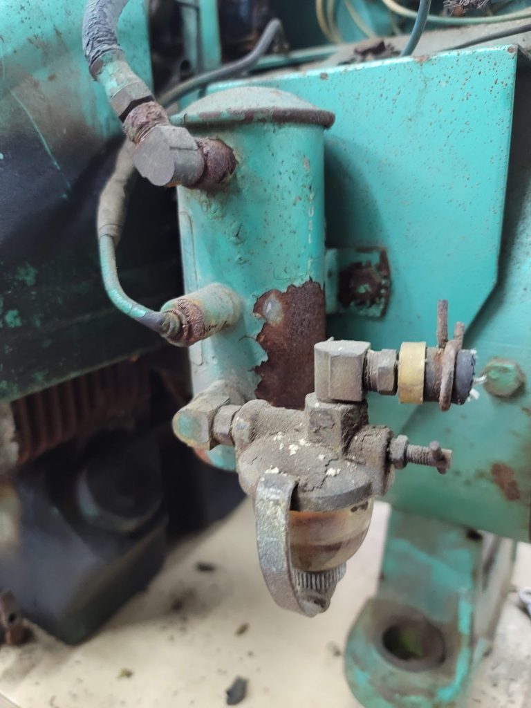
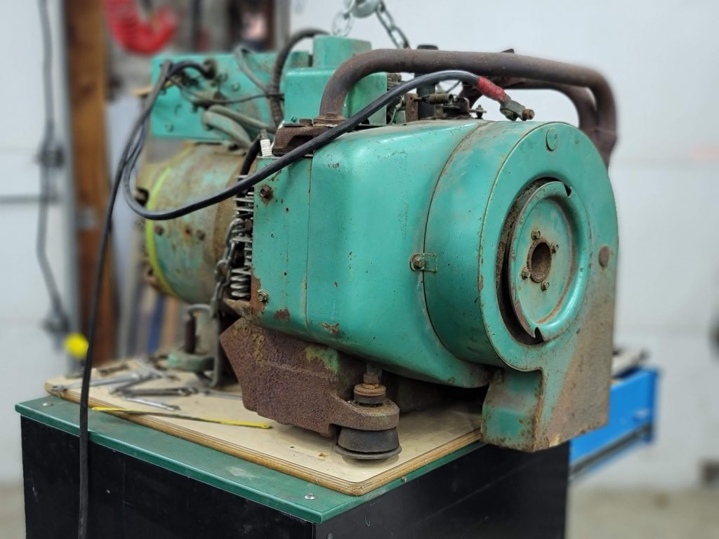
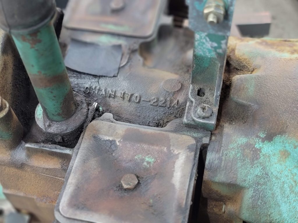
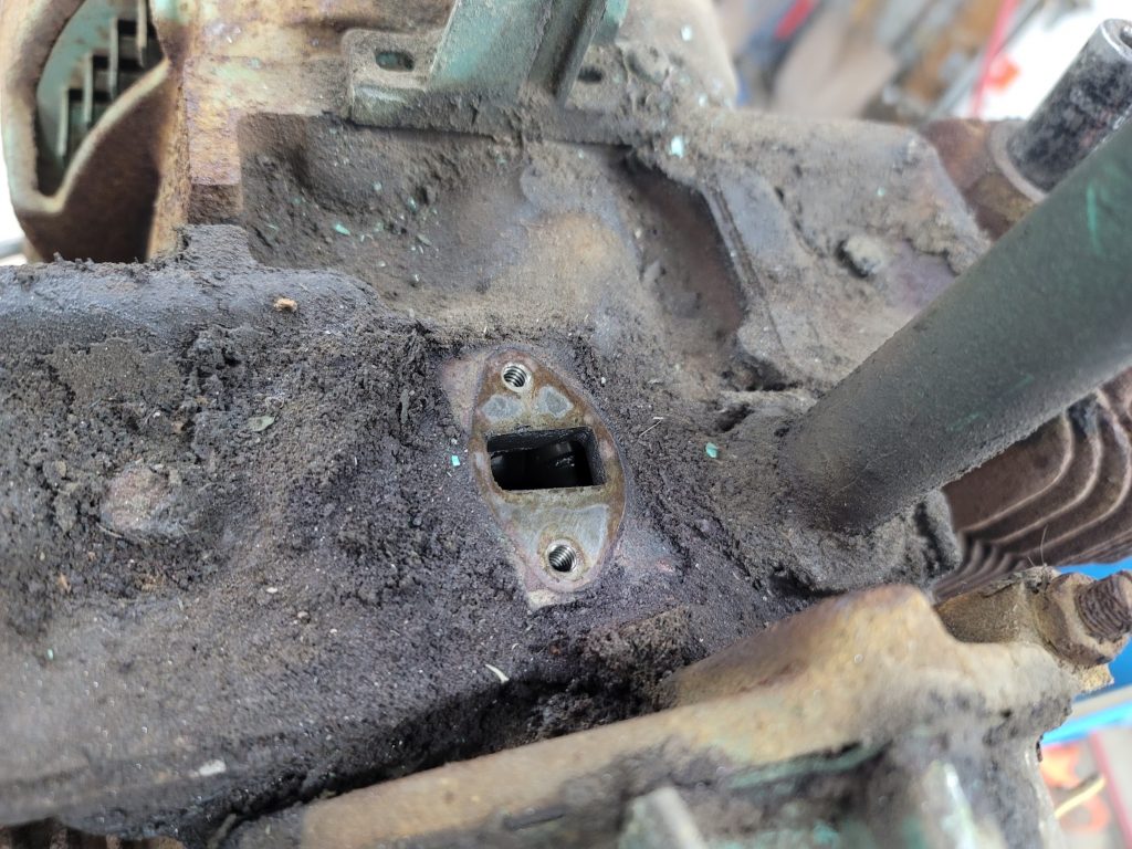
Here are some close up shots of how it started out. Next step is to pull the tins and poke around…
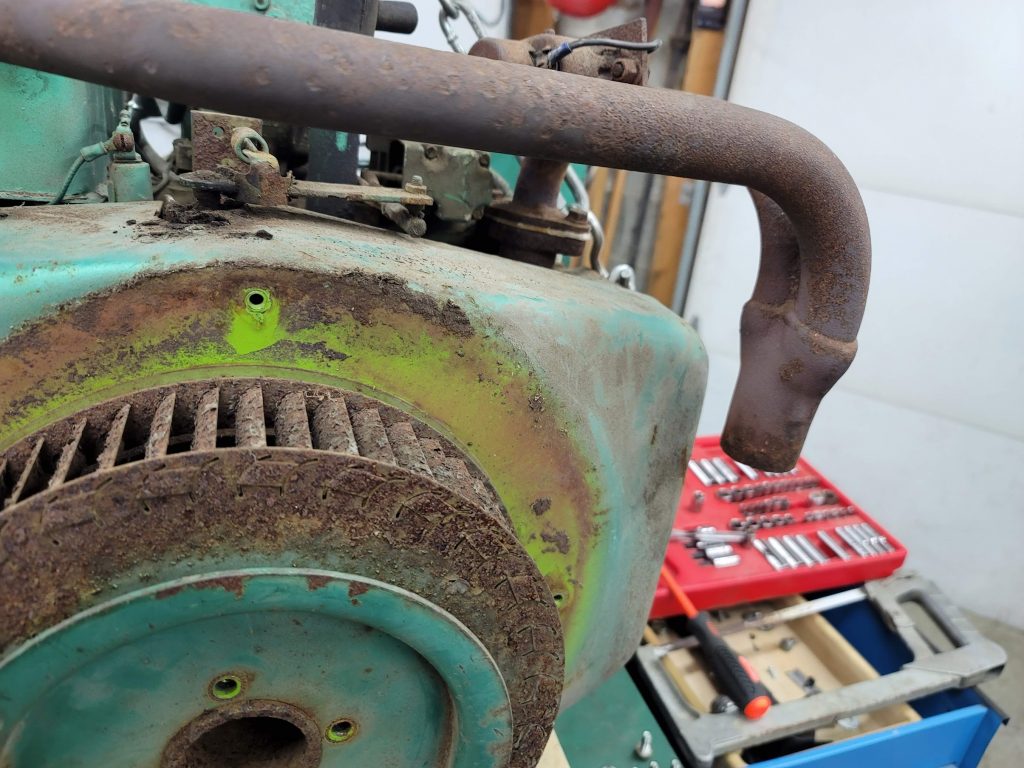
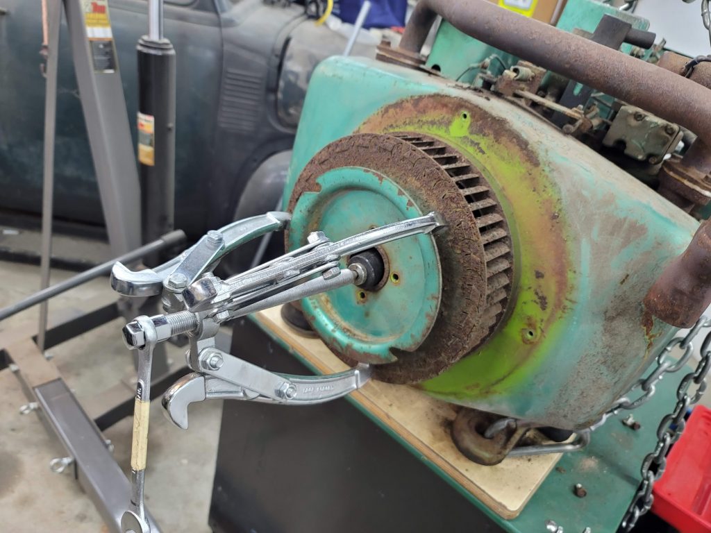
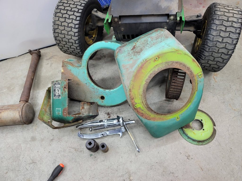
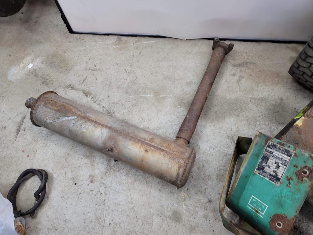
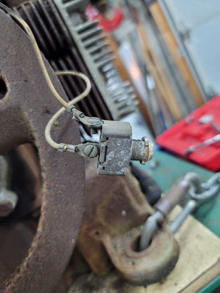
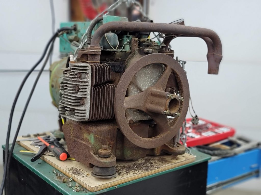
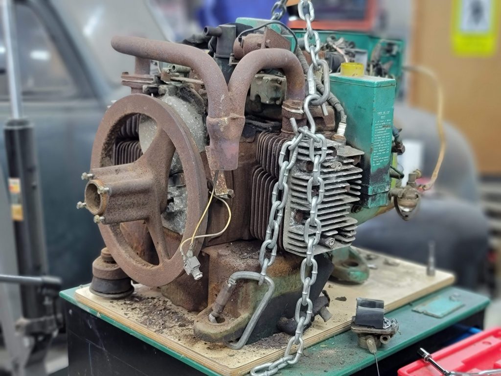
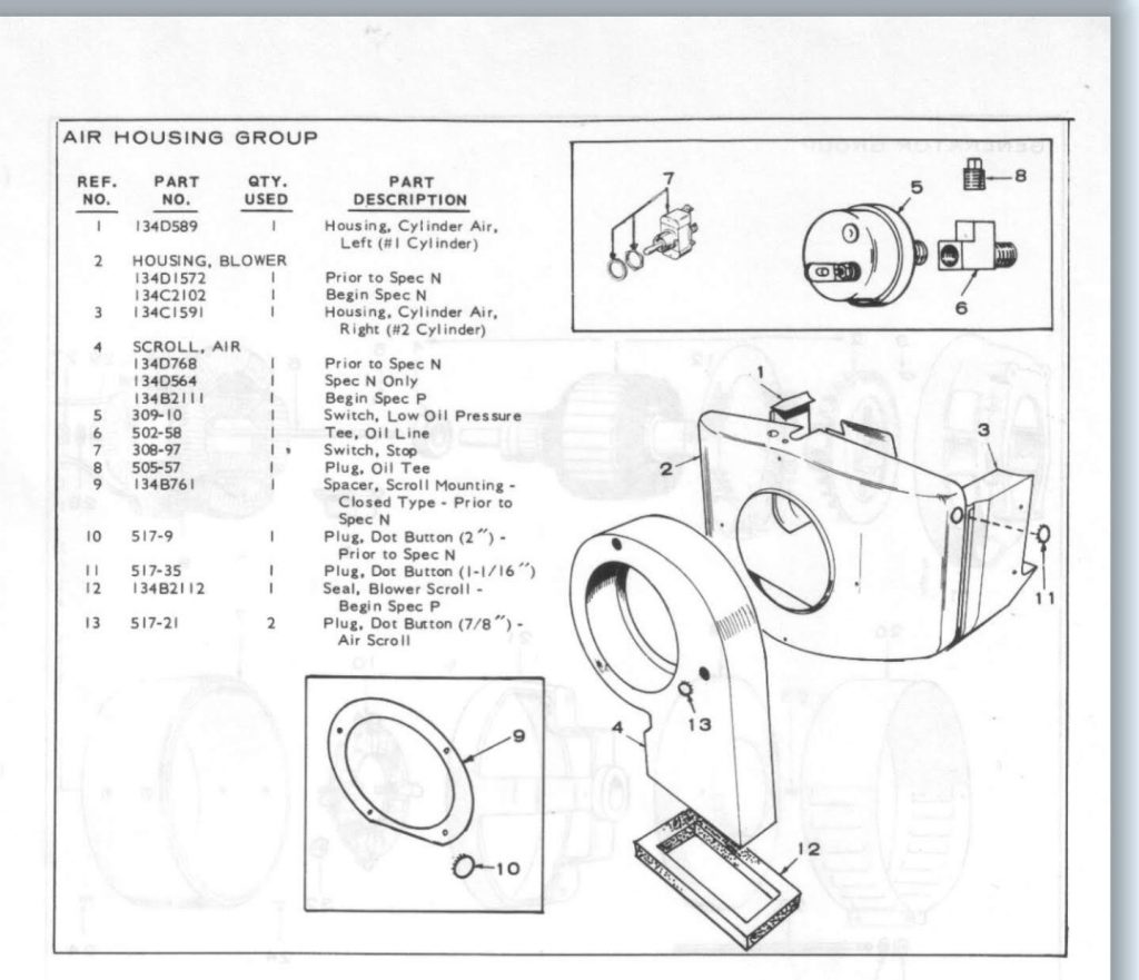
To my surprise, all he bolts came out, and I was able to get a better look at the internals. She is pretty rusty, but not beyond saving. The ‘vacu cool’ impeller was not wanting to come off, took lots of scraping rust, a BFH and a puller to get it free.
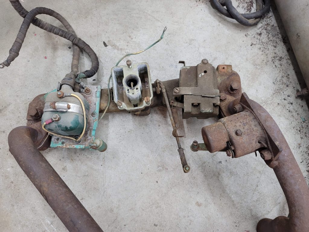
I then pulled the intake and exhaust manifold off, to start looking into the carb. NOTE: At this point I pulled the spark plugs as well and injected some ATF to help free up any stuck rings. Than gave it a few spins by hand.
The Carb was the first part of the project, a replacement carb is more expensive than many entire generators new! So set out to rebuild what I had. I cover that entire process here,
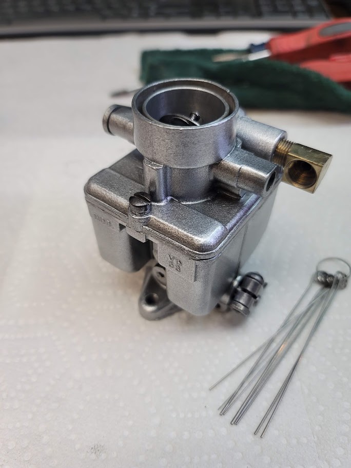
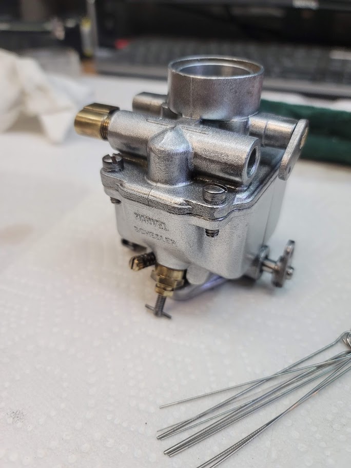
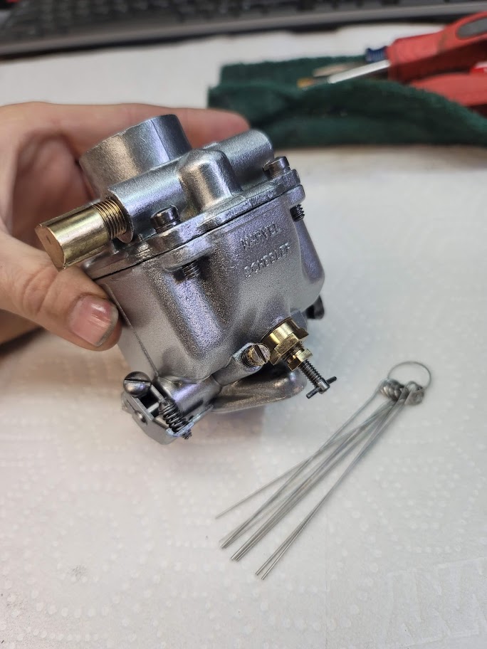
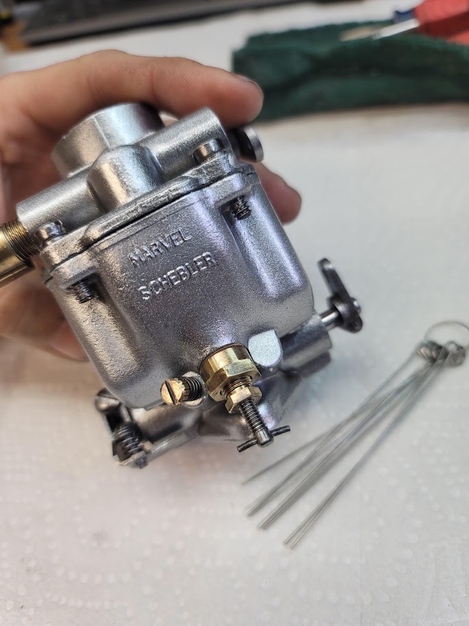
Here are some After restoration pictures of the carb from the other post for those who want to skip that part.
Next step was the generator section…
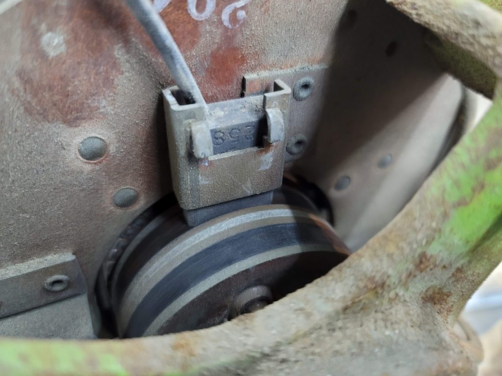

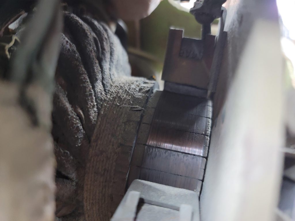
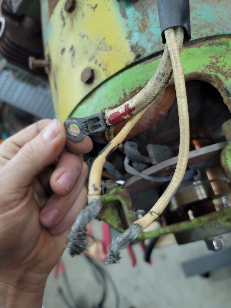
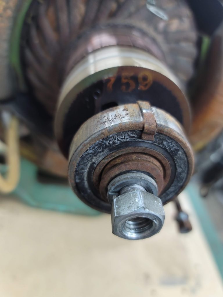
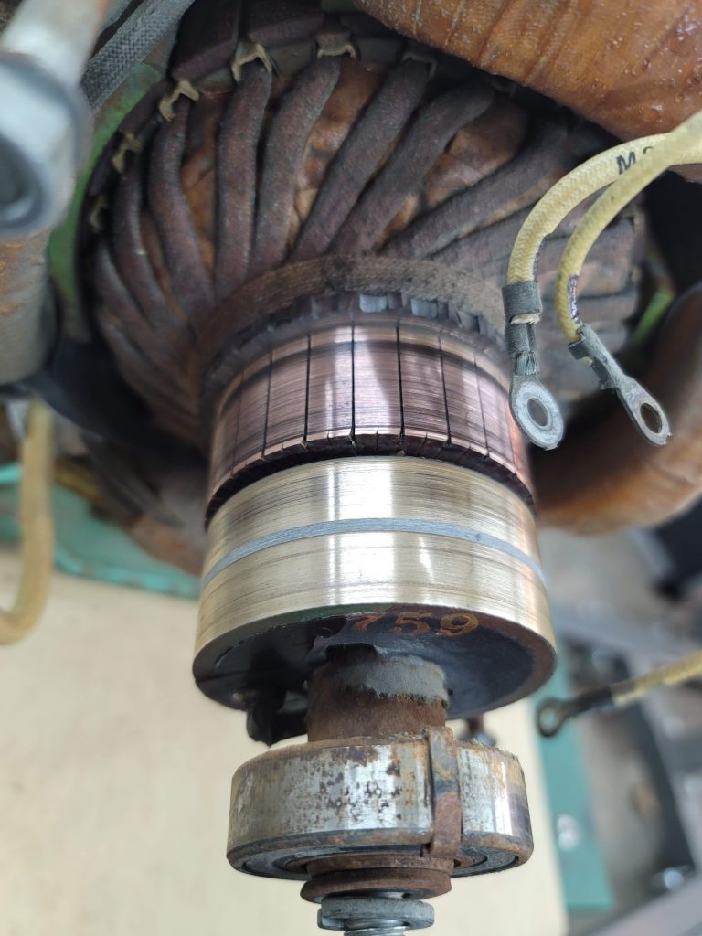

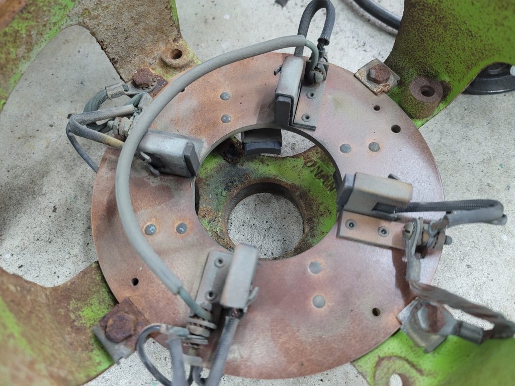
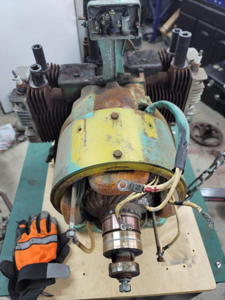
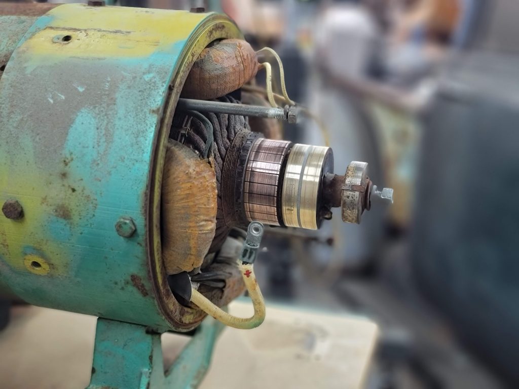
This was a PITA to get off, it was frozen on pretty good, application of a BFH and a puller I was able to get the back end off. 7 of the 8 brushes where seized in place, I was able to get them moving again, they look to have good life on them, that is promising that this genset may not have many hours on it! The rear bearing feels a bit crunchy, will try and pull some part number from it to be able to source a new one that is not stupid expensive Onan branded.
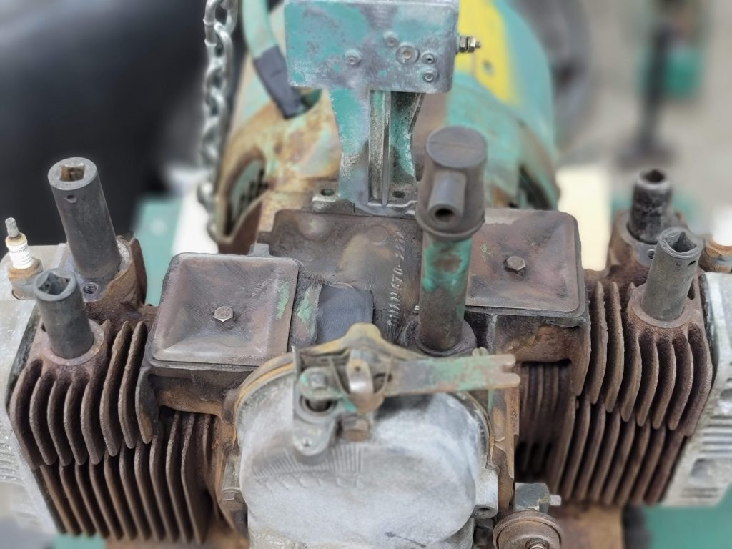
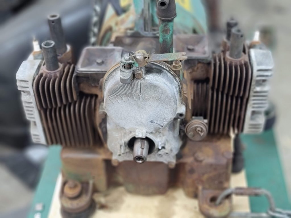
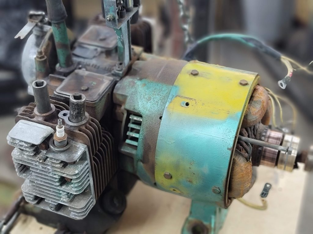

I then pulled the flywheel… Also a huge PITA, even with my largest puller it took a ton of PB Blaster and Hammer modulation to get the taper to break. I took a wire wheel to the unit to get the surface grime off, next step is to do some blasting to get to bare metal for some paint. I will pull covers and check valve lash, but that is about it, I do not plan to do a full teardown, for I feel this unit has fairly low hours. … I also do not want to spend a small fortune on a gasket kit!
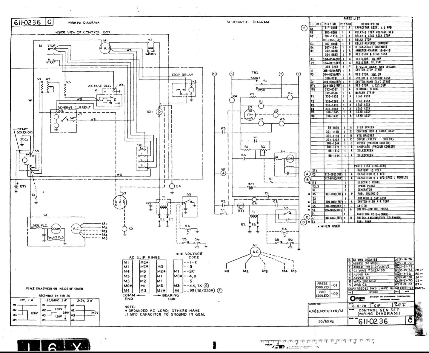
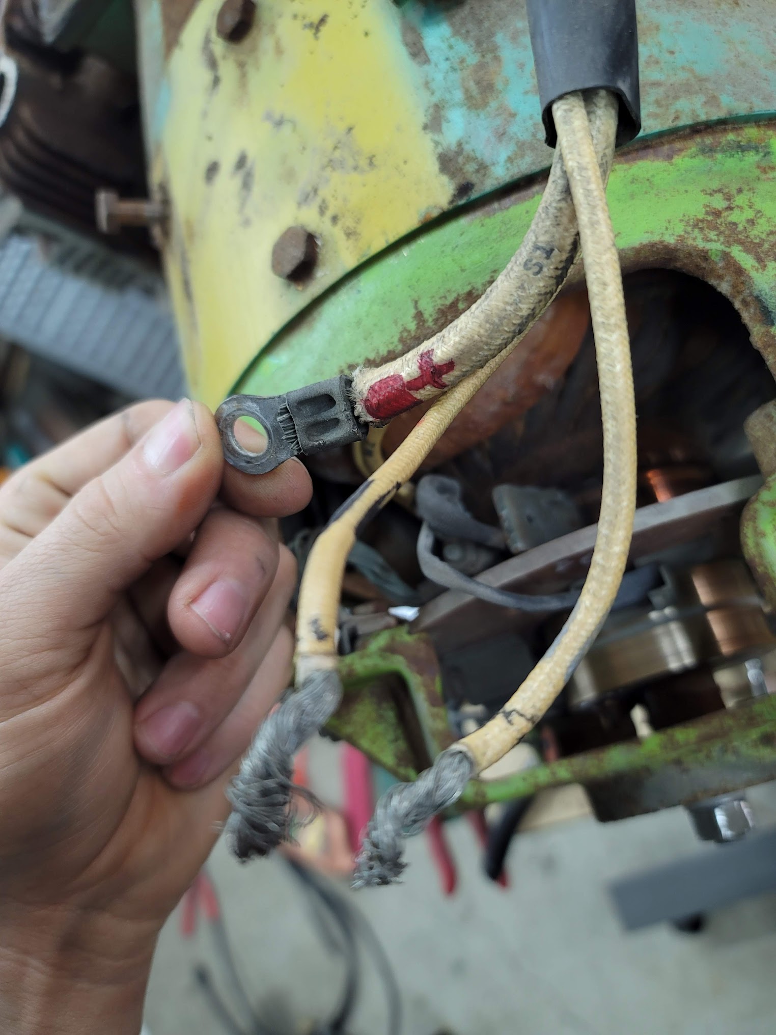
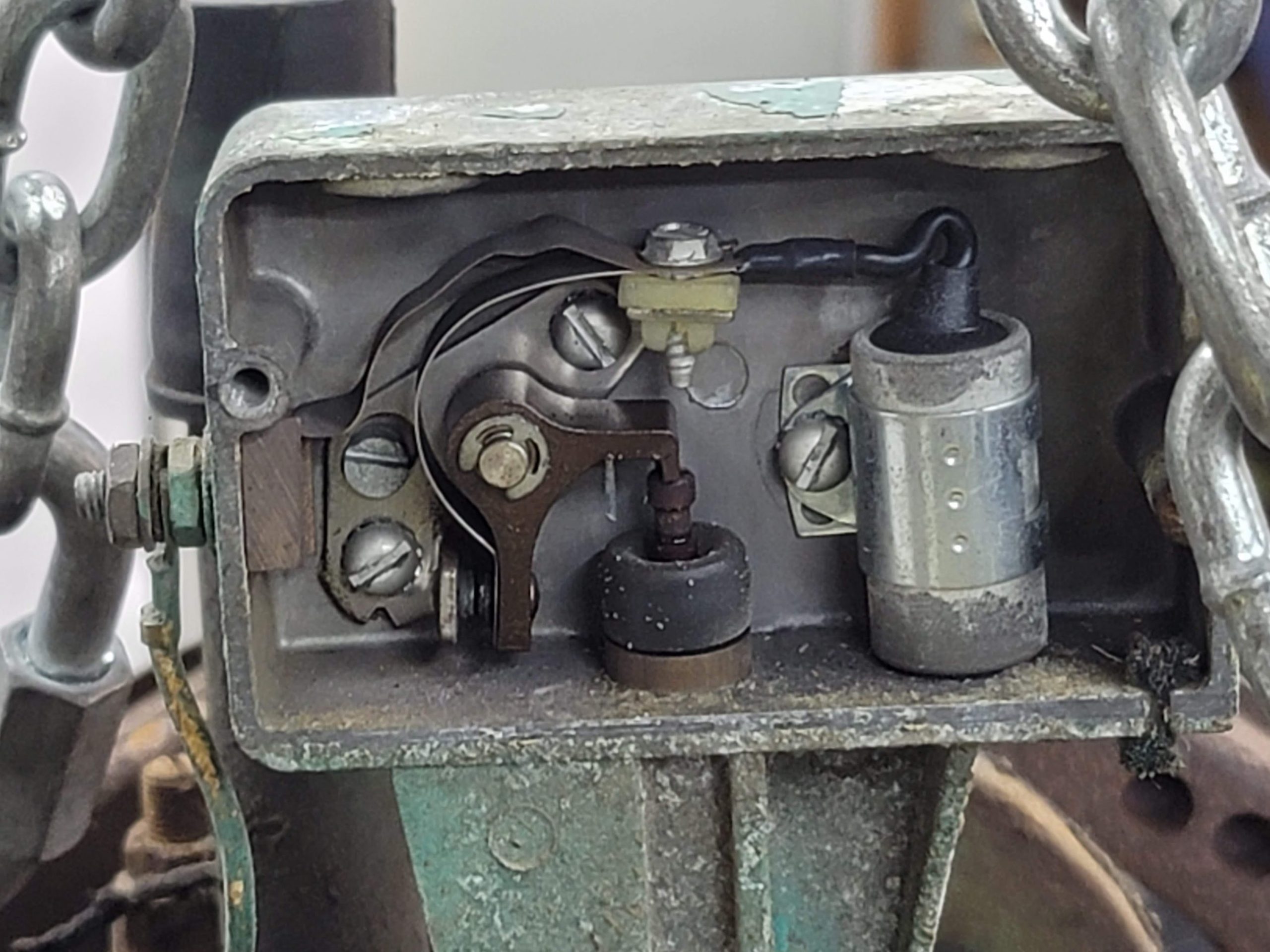
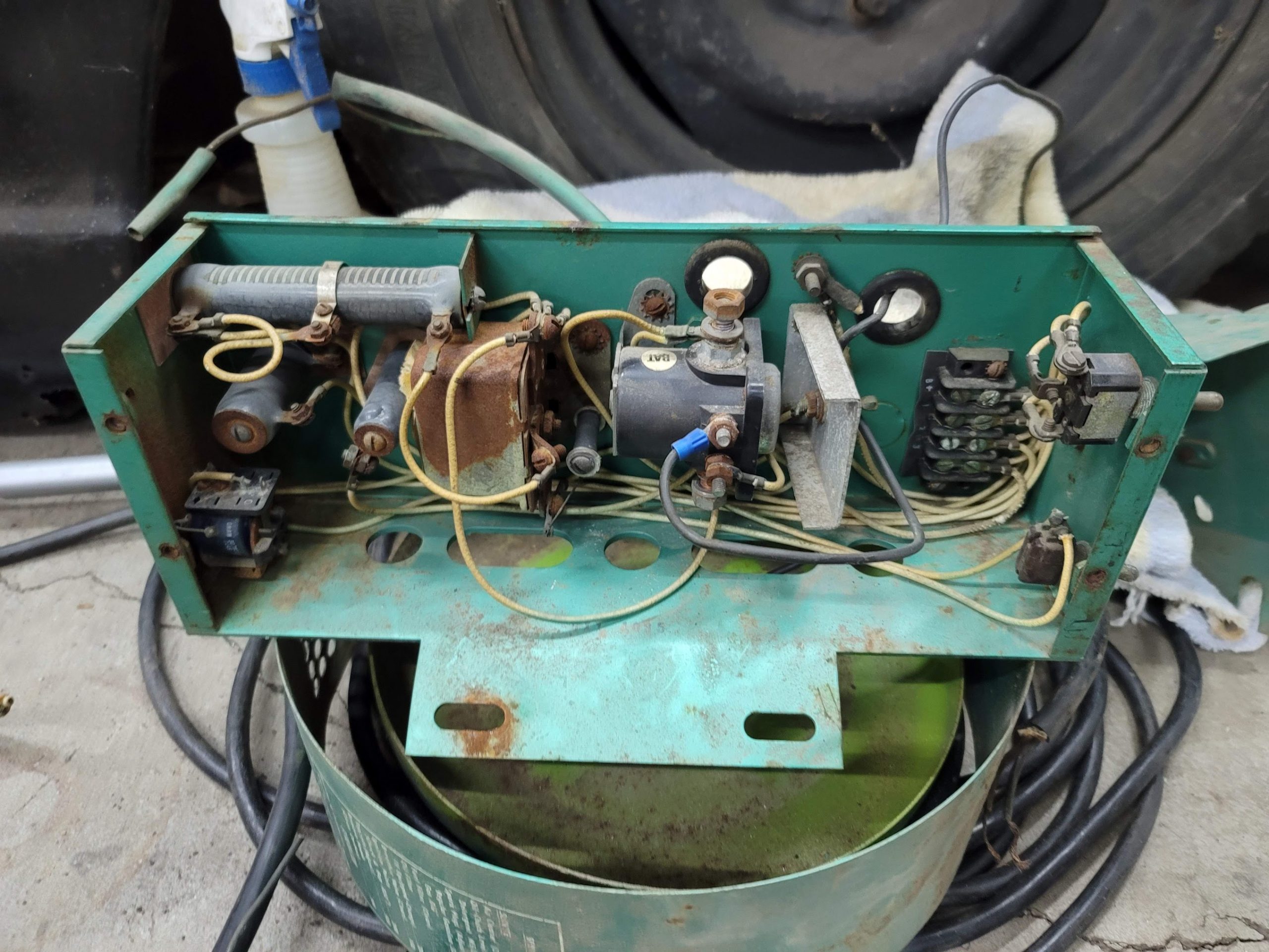
I did my best to fully check the electrical system, there was no spark, I checked and cleaned the points, they are working, but the Regulator/relay module ( rusty box ) is not outputting any voltage to the point system. I think I may replace all of this with a modern box and electronics. Most of what is here is pretty crusty as it is, and missing the side panel, is a good excuse to put a new power box on.


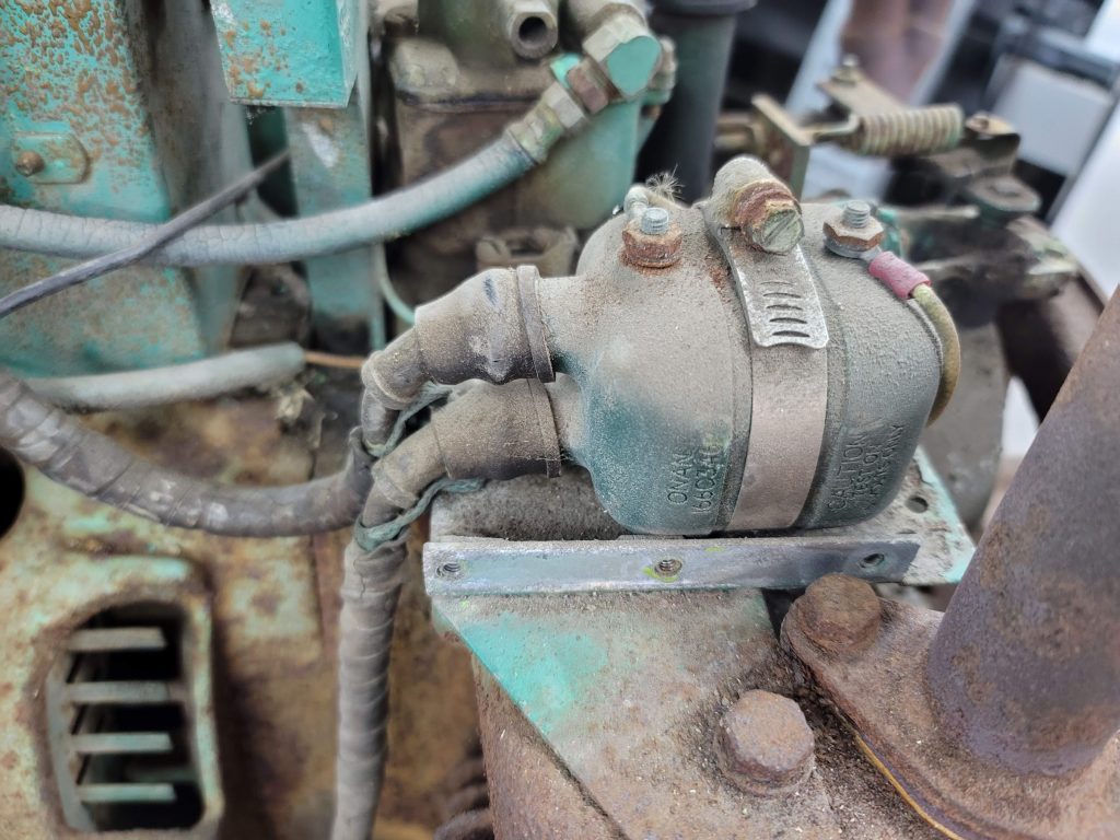

Not had a chance to check the old coil, but being that I need new plugs and wires, I am going to replace it with a modern 12V coil and ditch the resistor and old 6v coil.
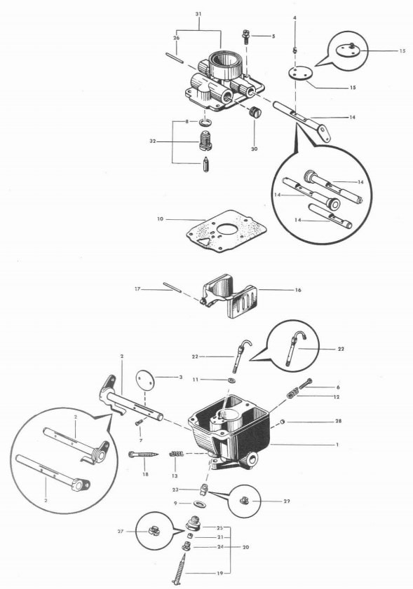
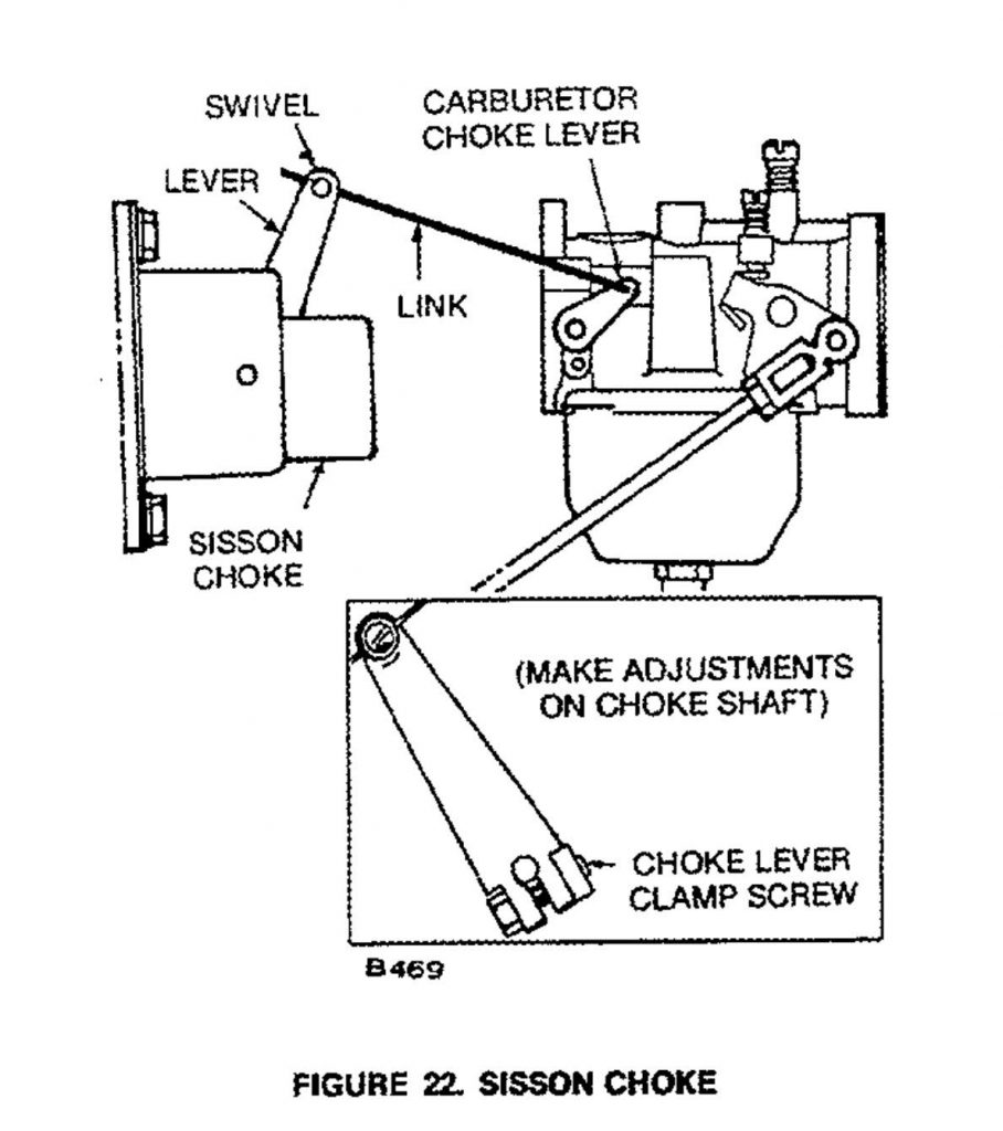

The Speed booster, and Sisson Choke are new to me! and very interesting, I may not keep the choke, for I will be at the genset everytime it is started, I do not trust auto starting something like this… Besides it is for power drops in the lab, I will be board with no power so starting the genset will give me something to do in the dark ha!
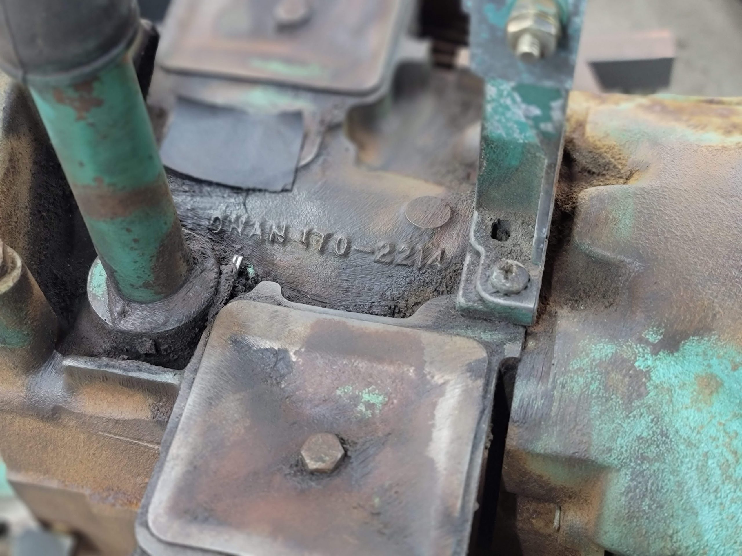
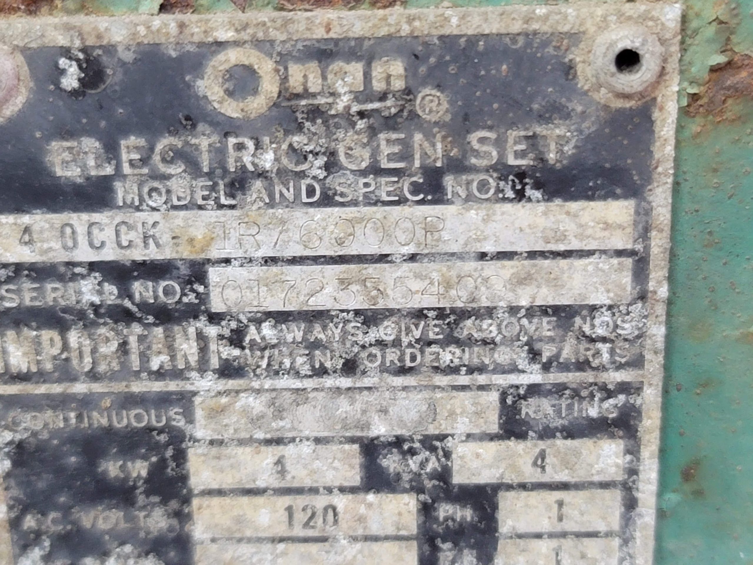
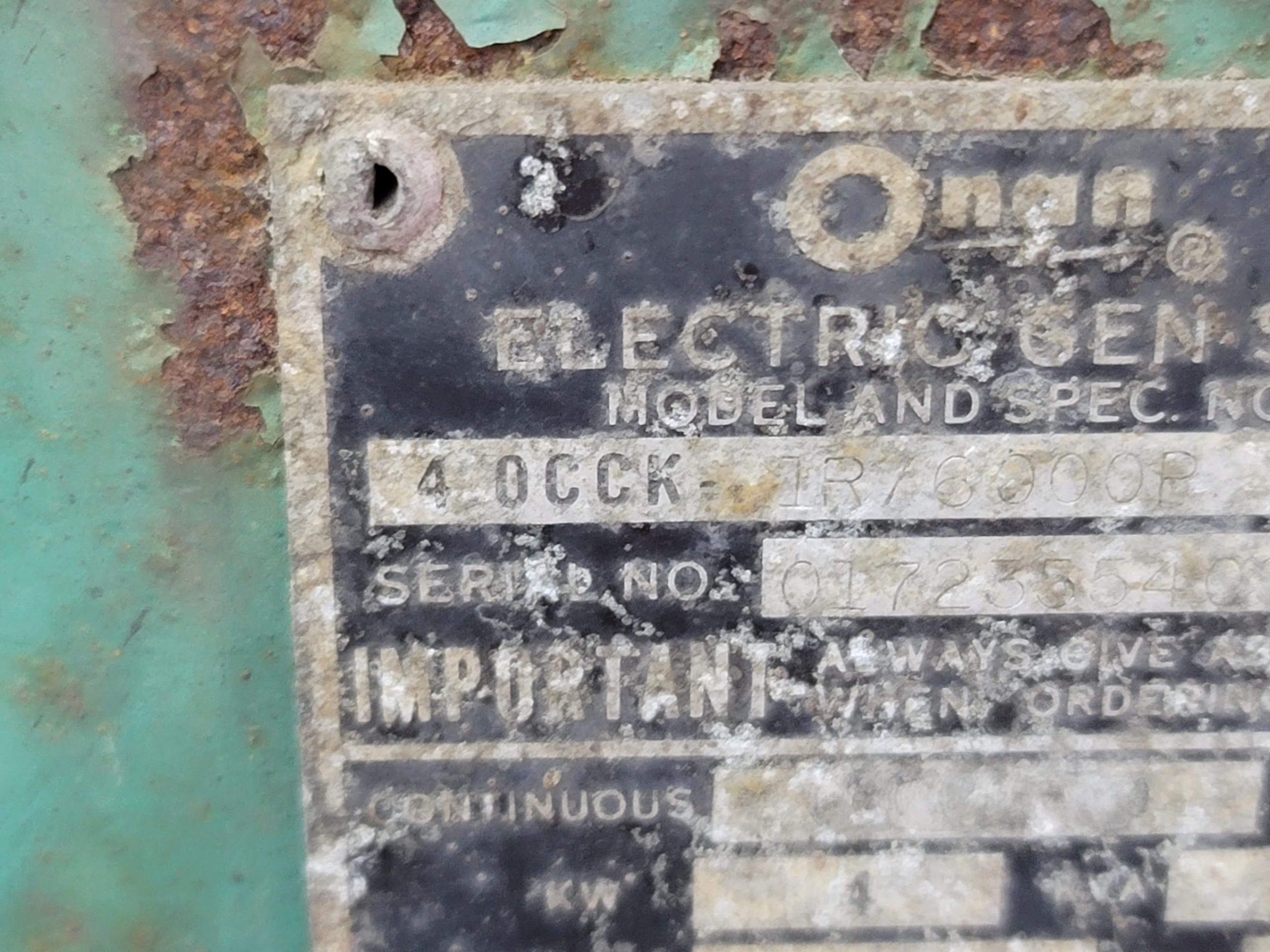
Would love any help in hunting down service manuals for this unit, or honestly any more info on it! I will take it all! Post a comment below and I can email you back if you would like to send files that way!
There is much more to come! Will be picking up high temp paint this weekend, and will start getting some more parts on order.
Stop back often for updates!
Here is a video of the first test after cleaning the slip rings and armature, looks to spin good, so the motor/gen may still be good electrically!
UPDATE: 1/2/22
I started taking apart the exhaust/intake manifold assembly.
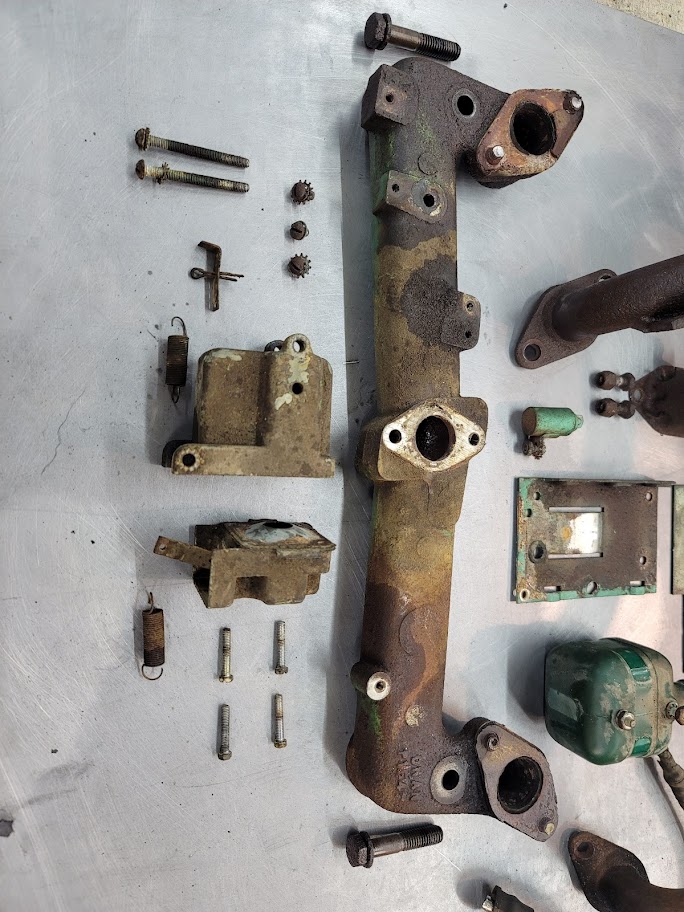
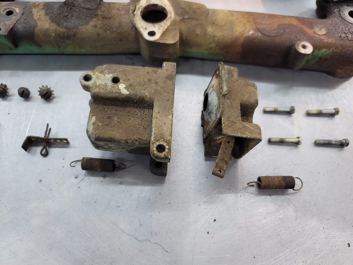
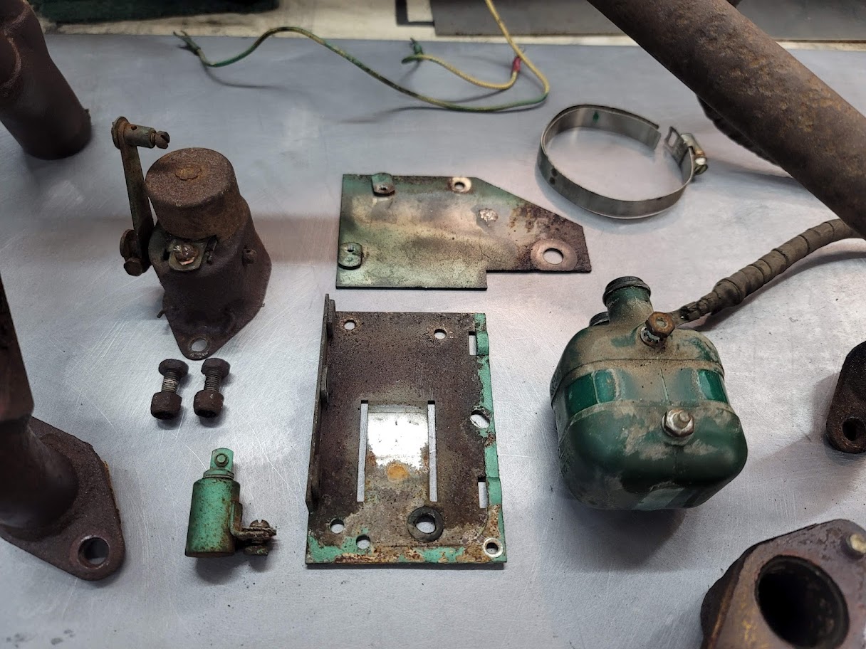
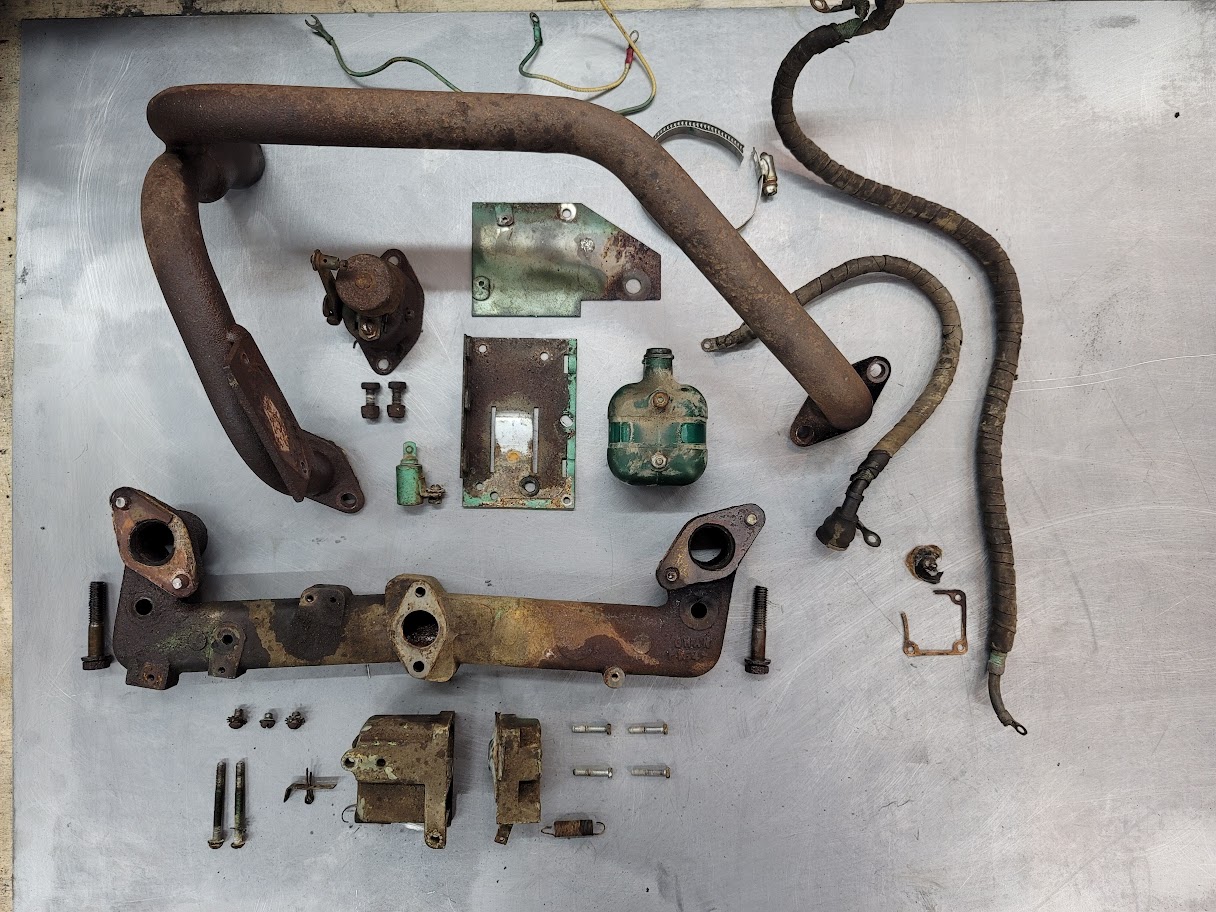
Those keen eyed may notice something on that exhaust side… yup.. every bolt snapped.
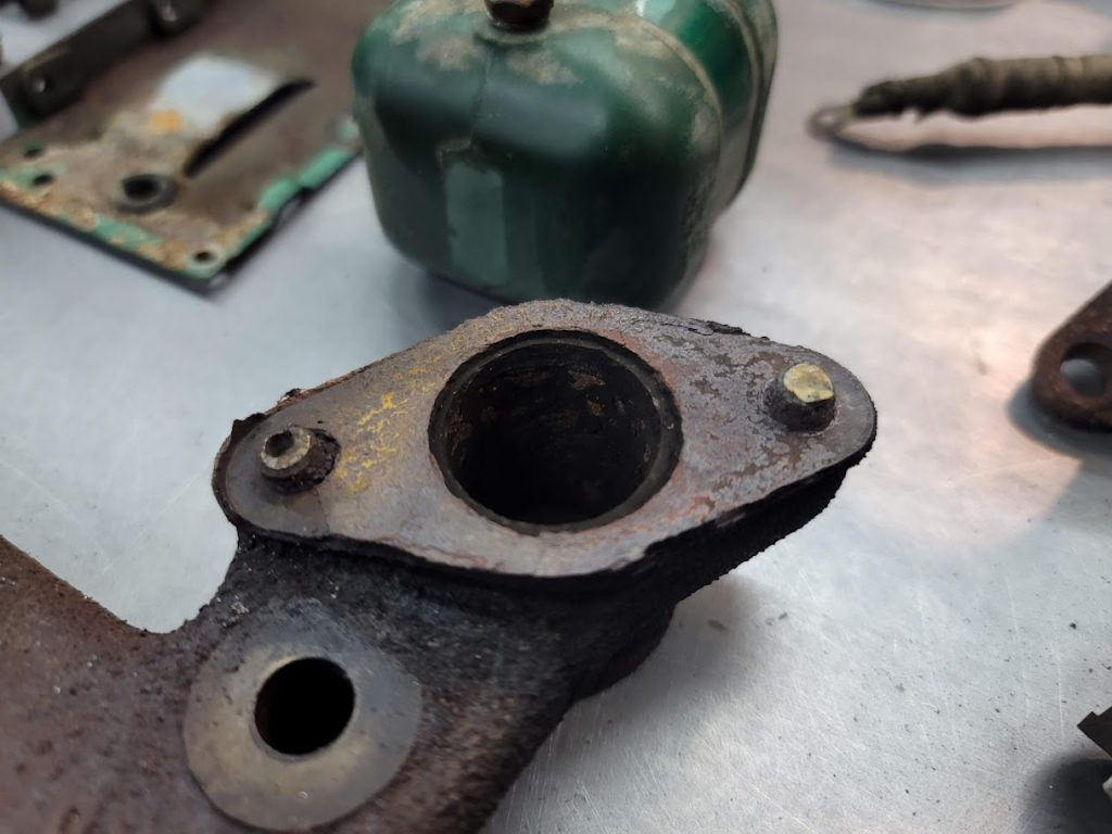
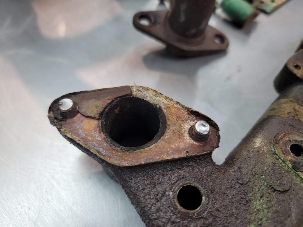
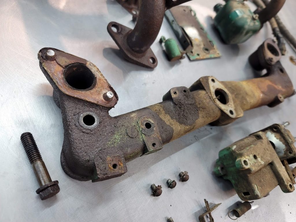
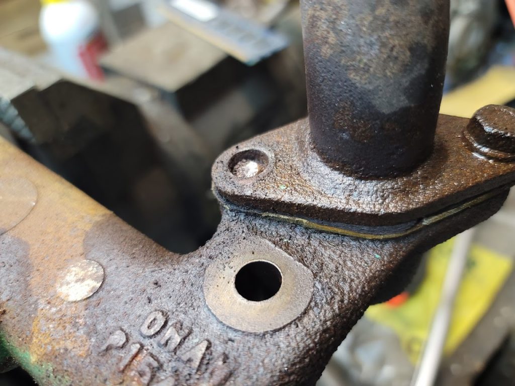
Even with heat ( Propane ) and PB bath, hey just spun the heads off with zero force. … time to extract some broken studs!

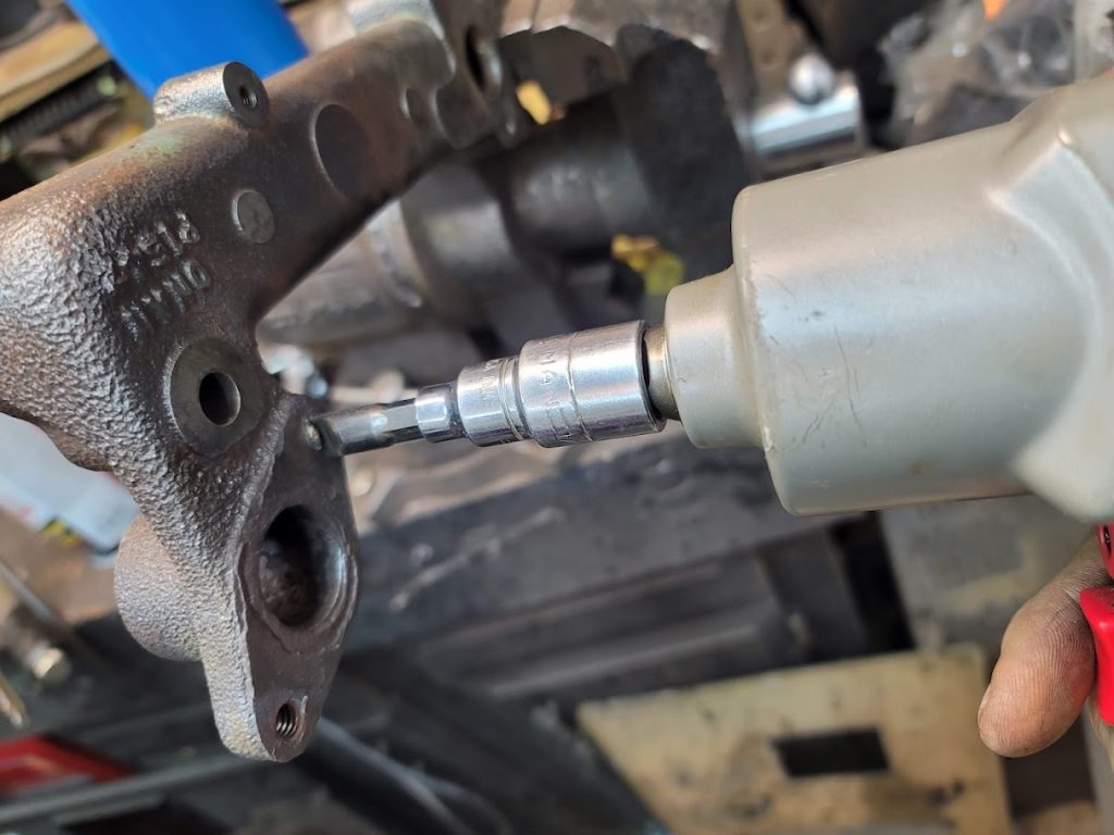
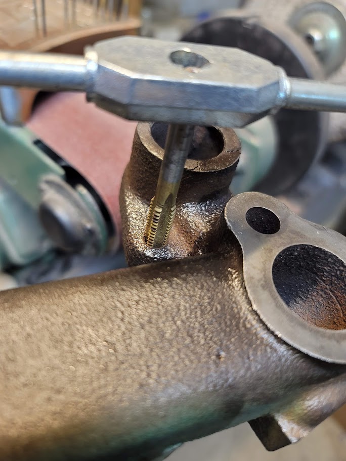
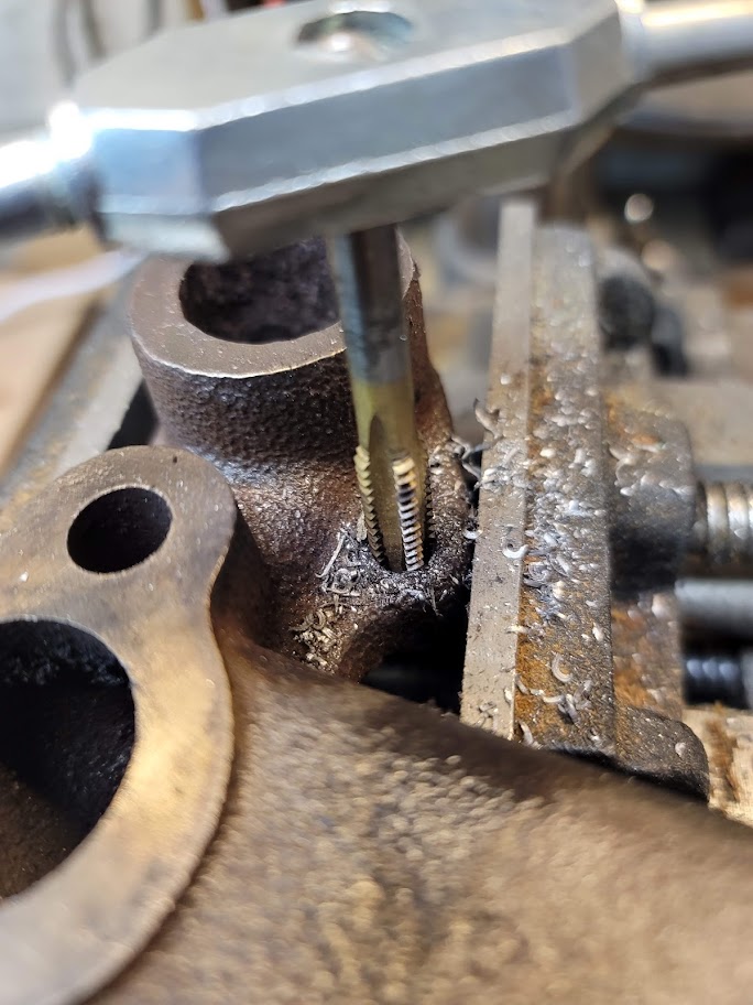
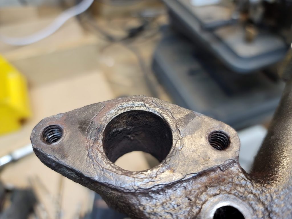
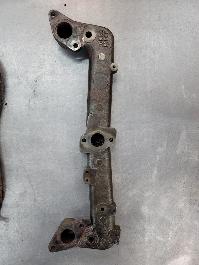
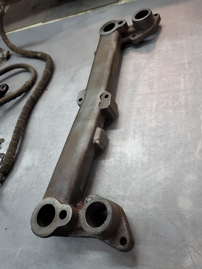
It was cold in the shop about 10F so that did not help things, I was being lazy and did not want to dig out the entire acetylene torch set.. well, I did and man it made short work of the frozen bolts. ( can’t be tights if molten! ) I had one that would just not budge, it had become one with the metal.. so drilled it out and re tapped the hole, even ran the tap through all the other holes to clean it up. A hit with a wire wheel later, and she looks much better!
I tried to find a new gasket kit for the exhaust manifold and they are not made any more and NOS ones are $15each! wow!
So Time to fire up the drafting software and make my own!
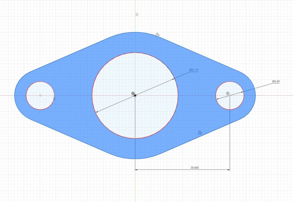
This looks good, now to grab some old copper sheet punch scraps, and do some cutting!
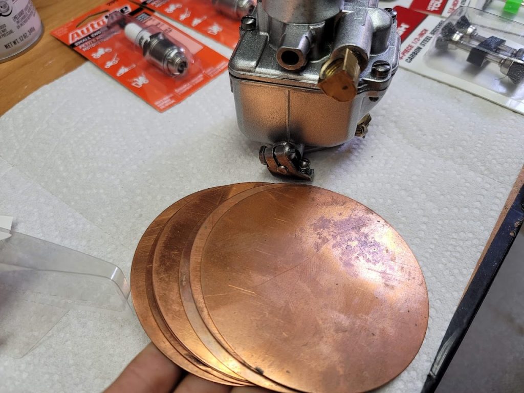
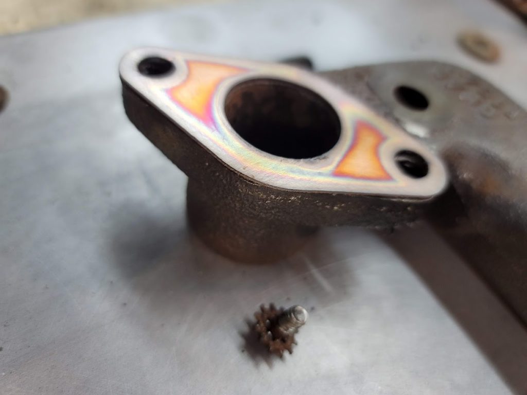
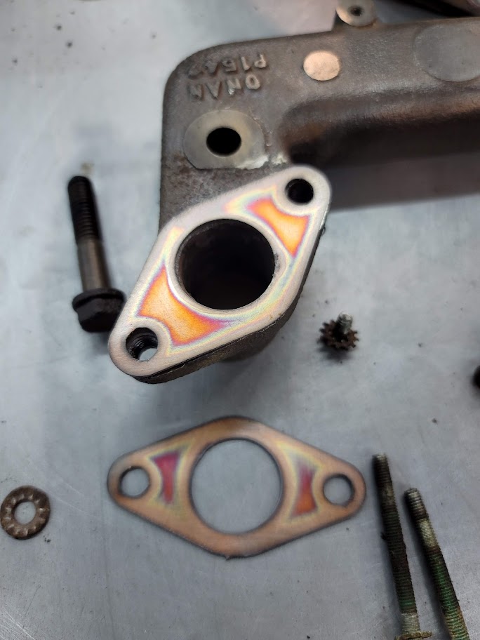
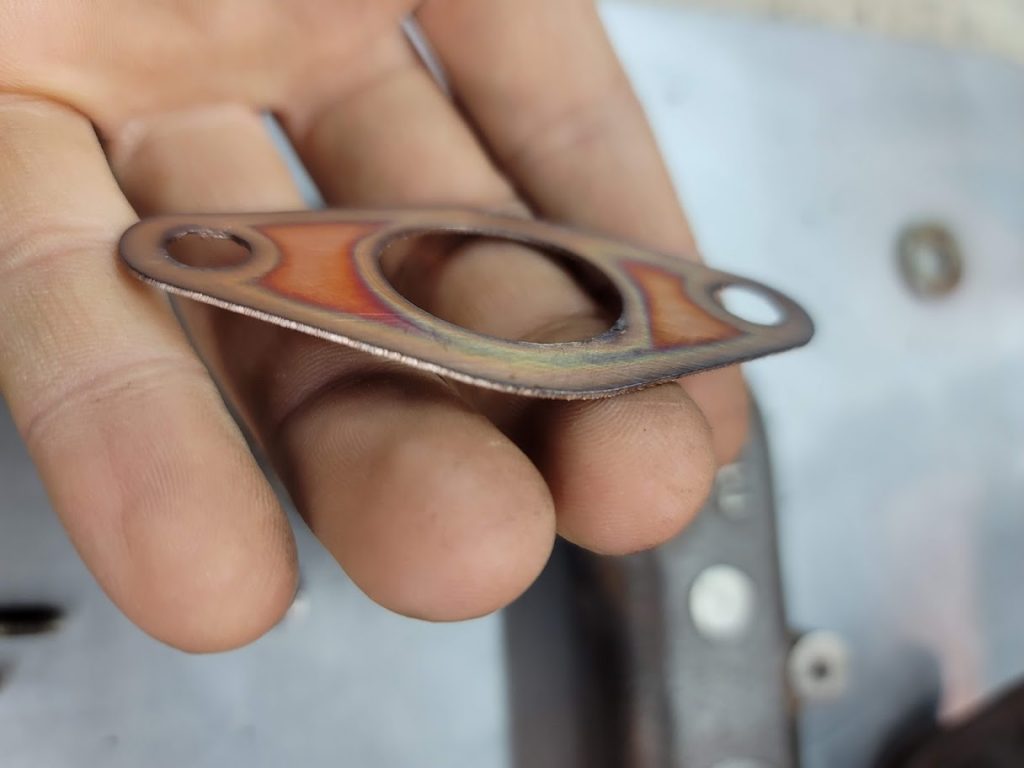
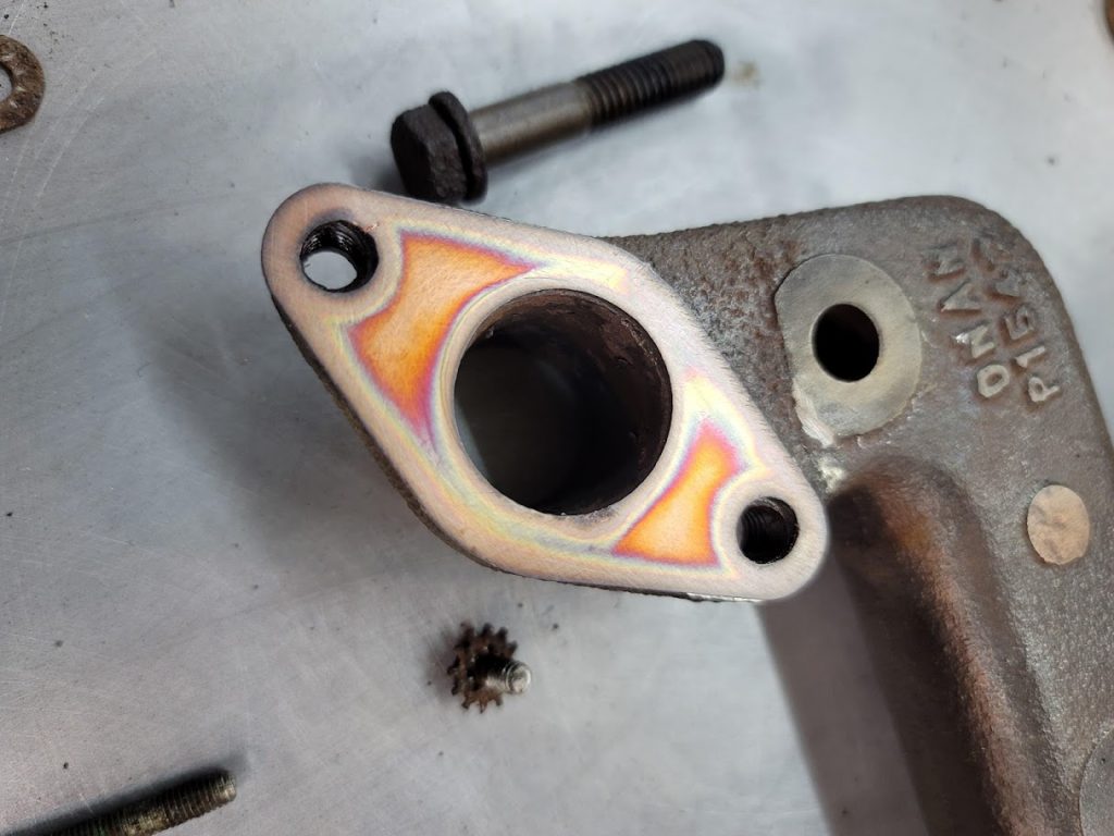
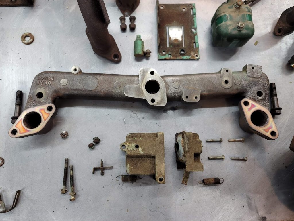
They fit! I know copper is not the best gasket for small engines like this, but it is worth a try for close to free!
Next step is to prep the block for paint!
UPDATE: 1/26/2022 Started work on the generator back end and brush assembly.
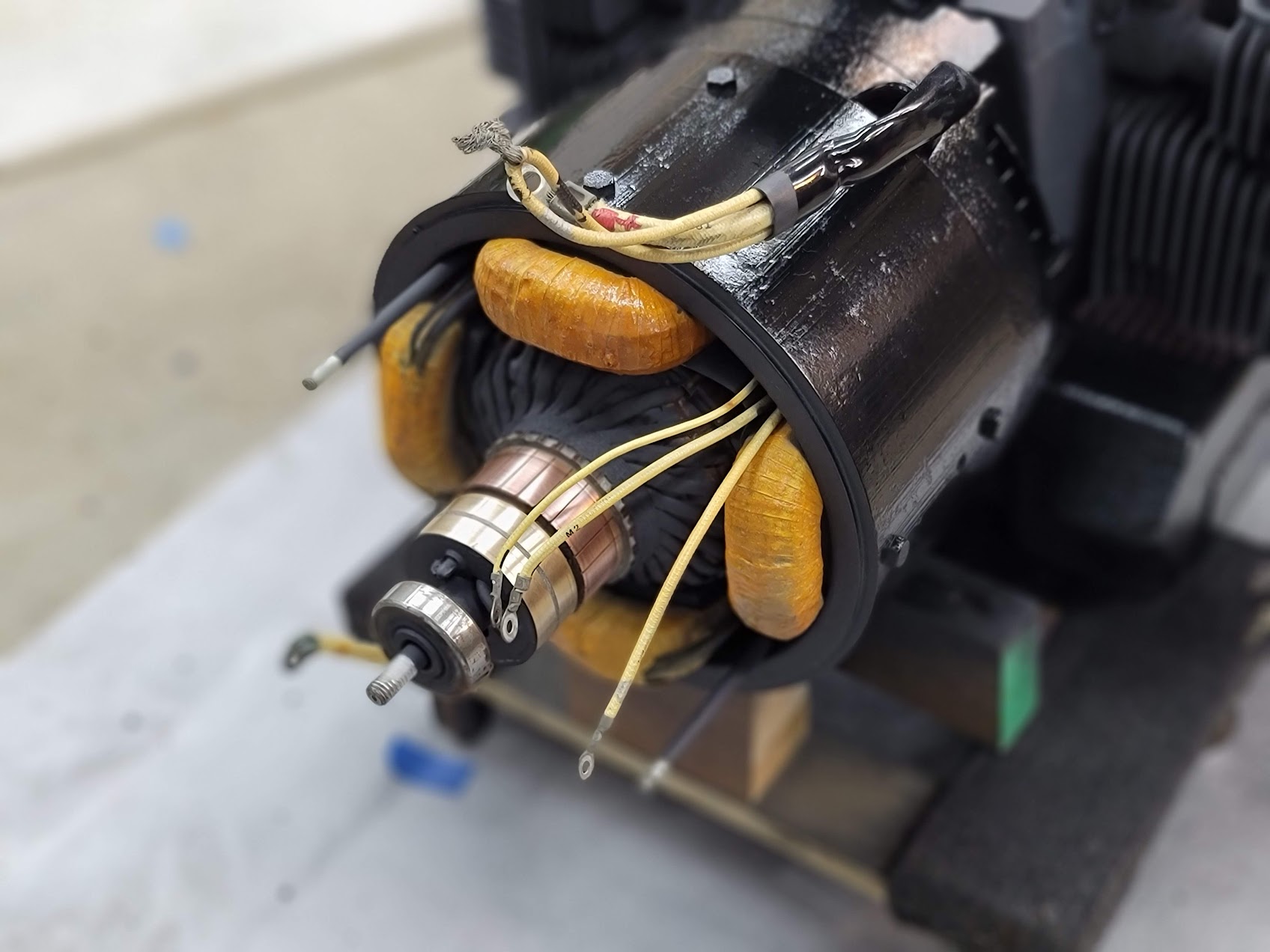
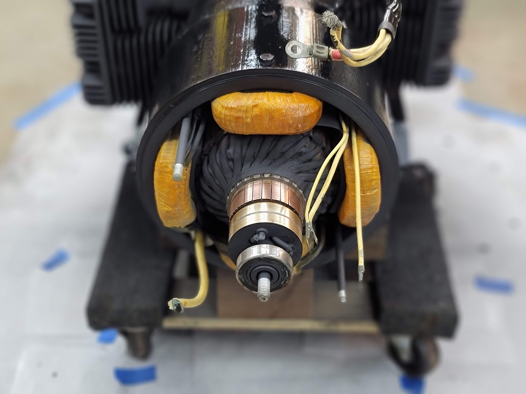

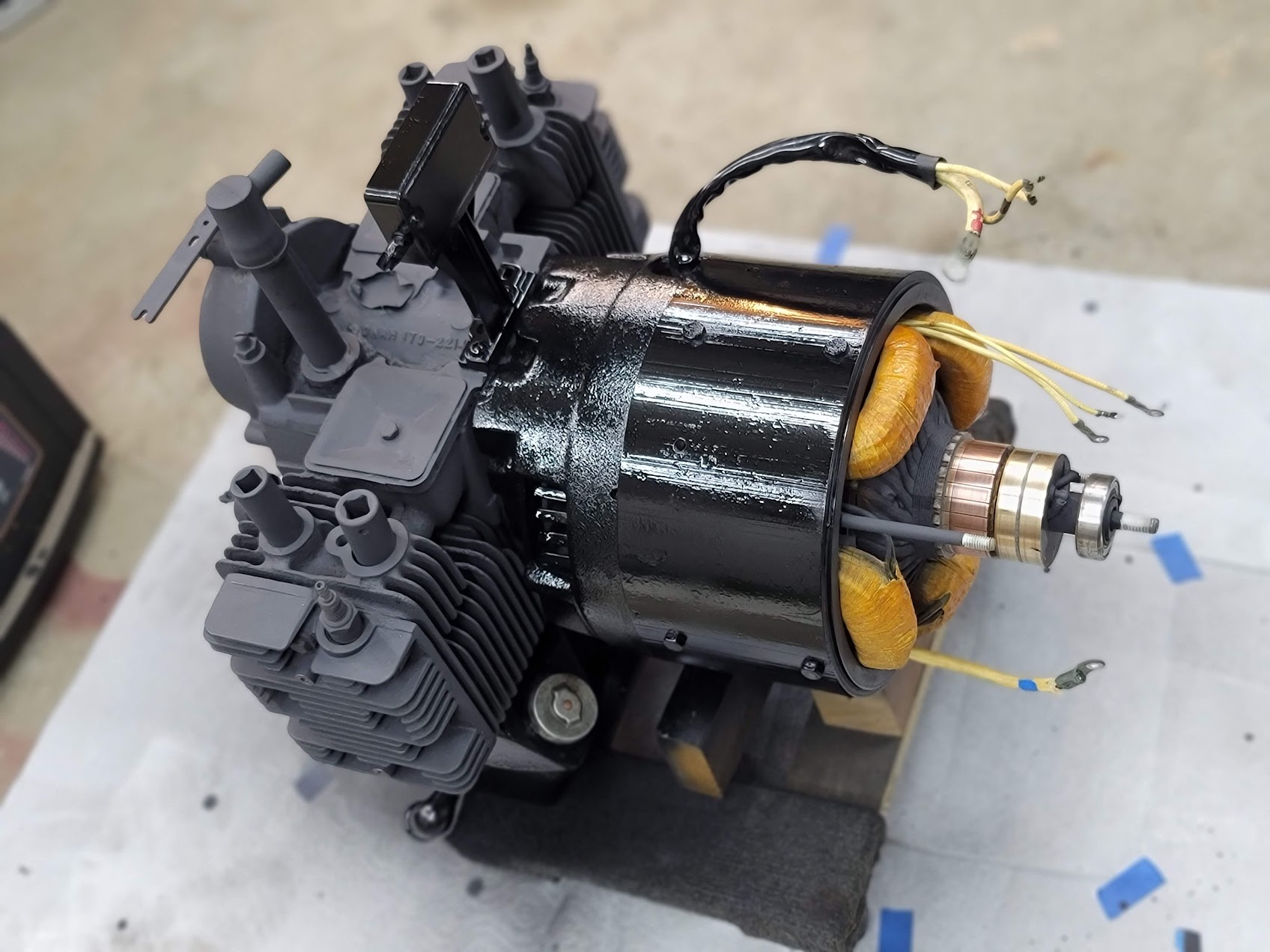
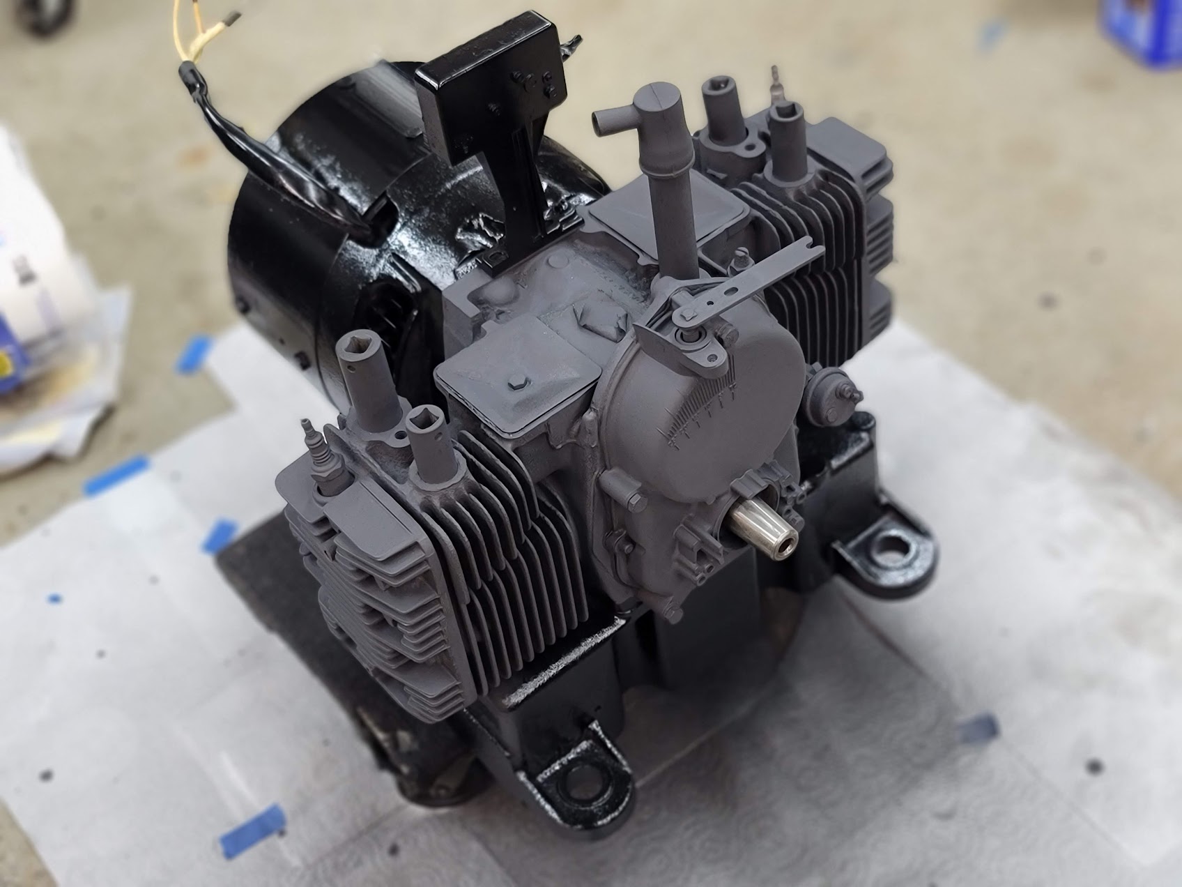
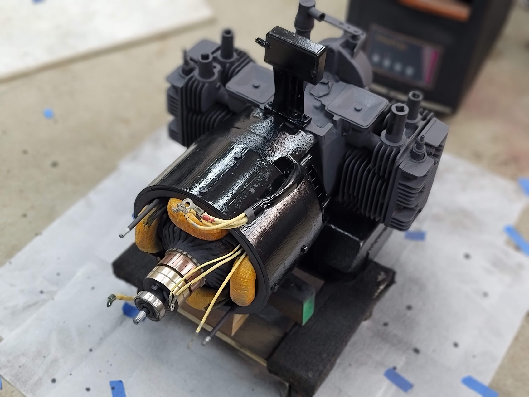
Got the chassis stripped down, and in primer and paint, I am going with a weird two tone loo, with Matt and Gloss black, ( Fingers crossed it looks neat when done ) Still need to finish lapping the armature, and replacing the rear bearing. But the motor and coils cleaned up nice! The tins and other parts will be gloss.
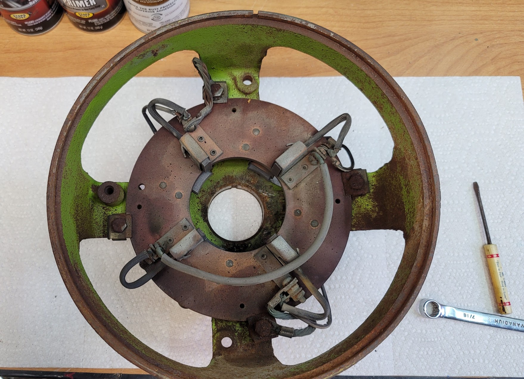
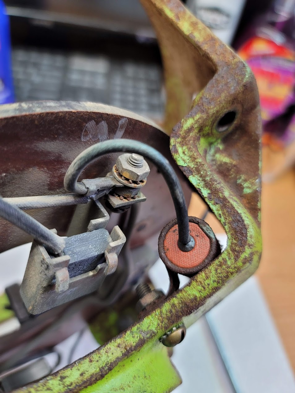
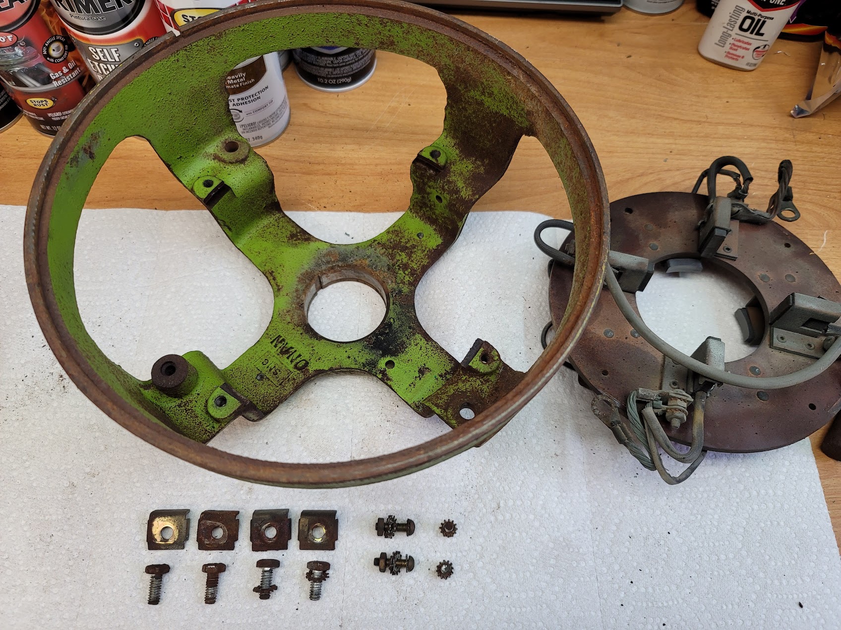
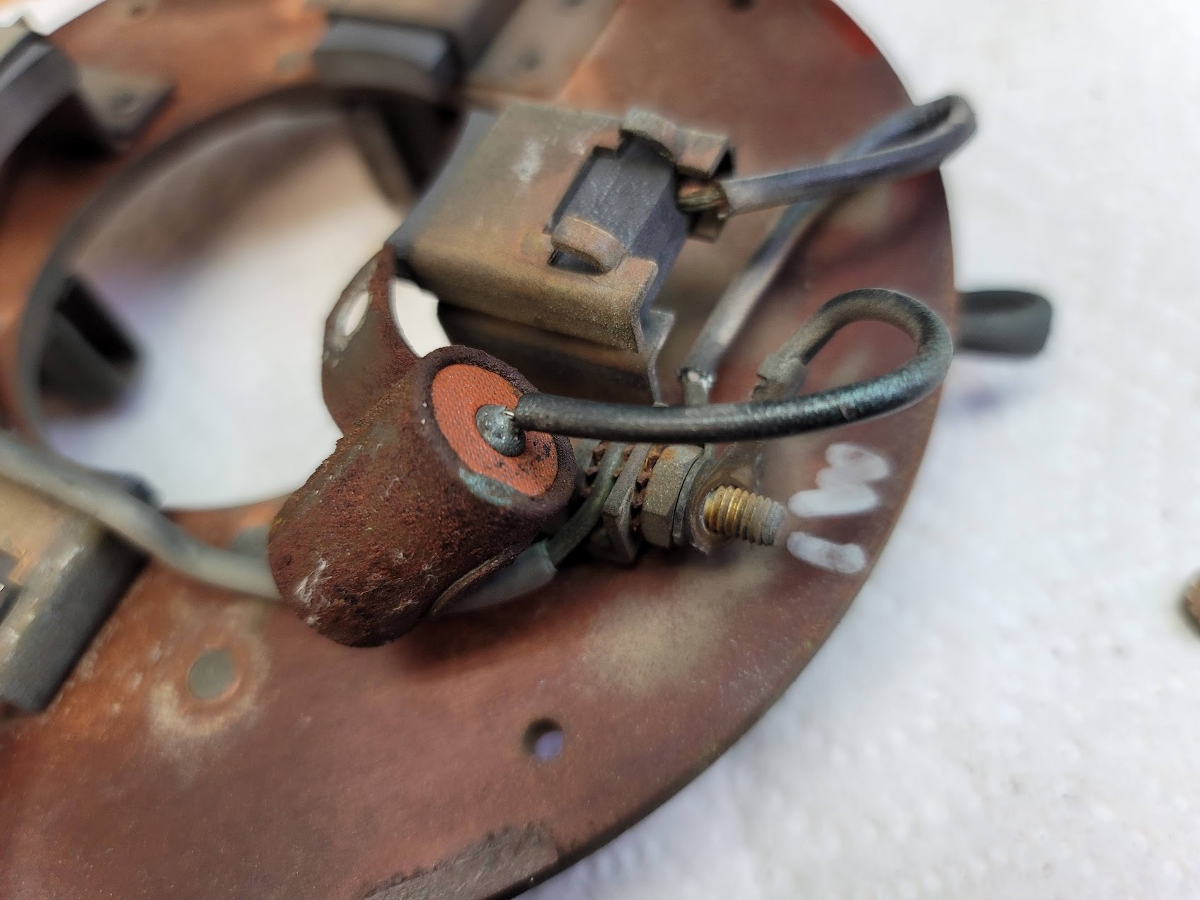
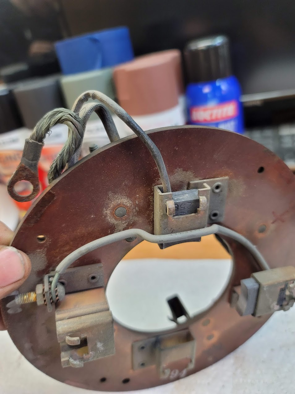
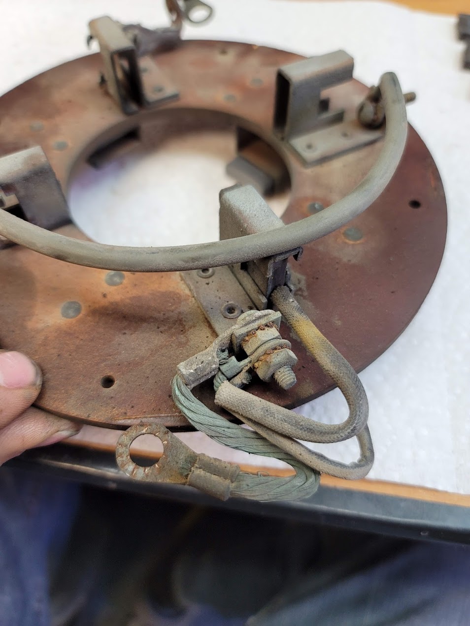
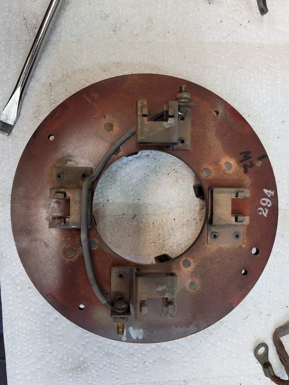
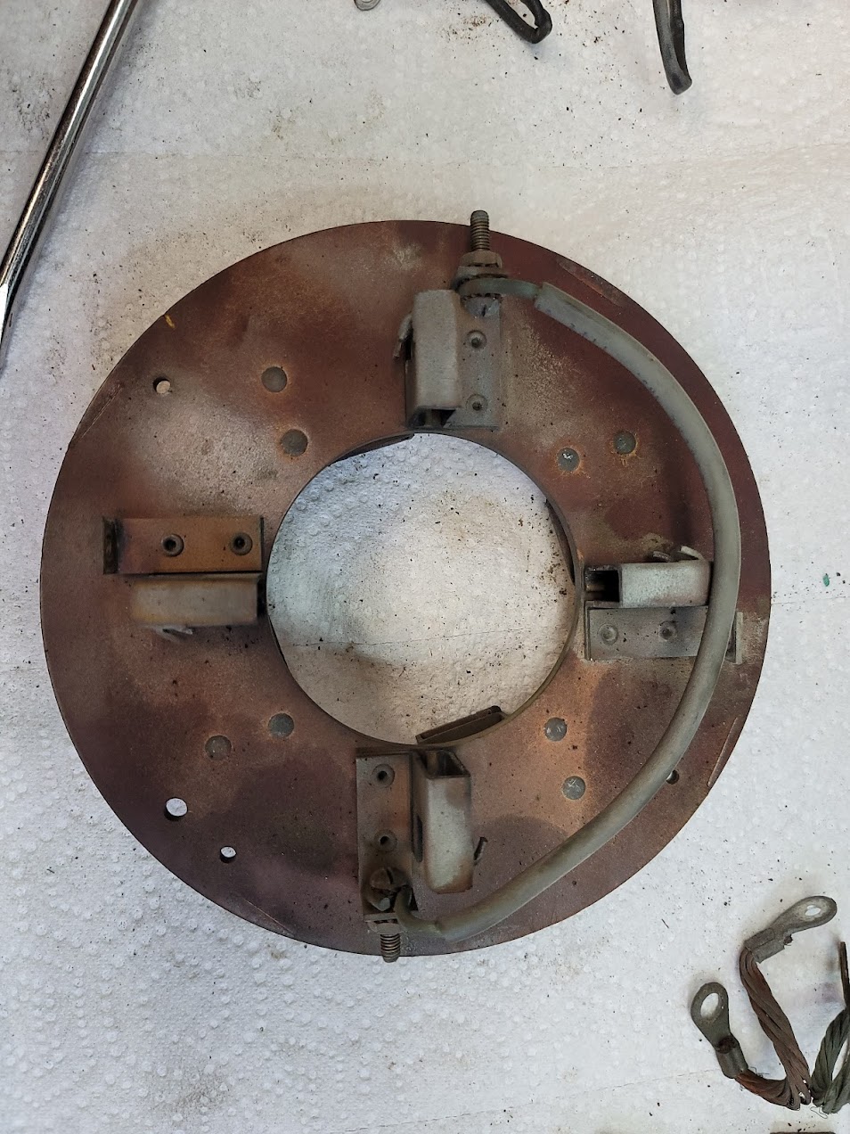
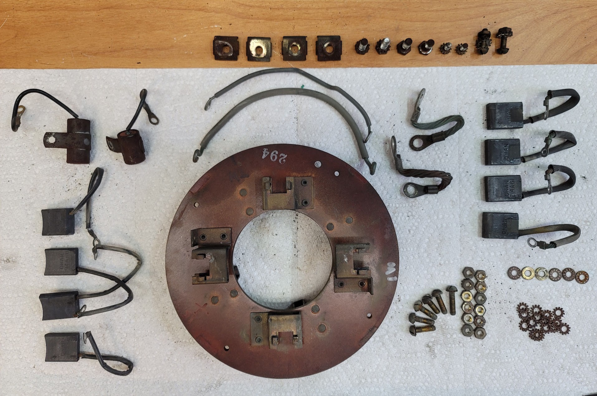
Here is what I stared with, Did a full strip down of all the parts to prep for restoration.

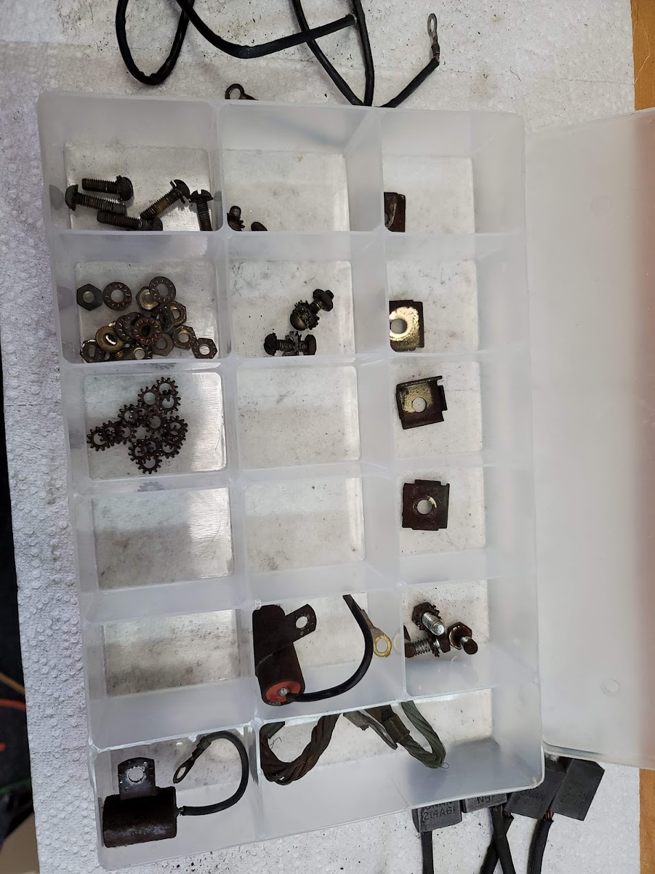
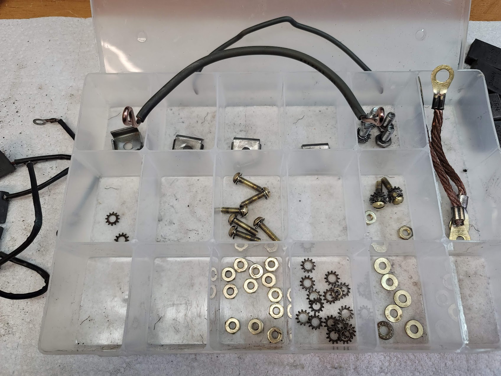
Here is a before and after of the hardware, each piece was wire wheeled by hand, took the better part of the night!
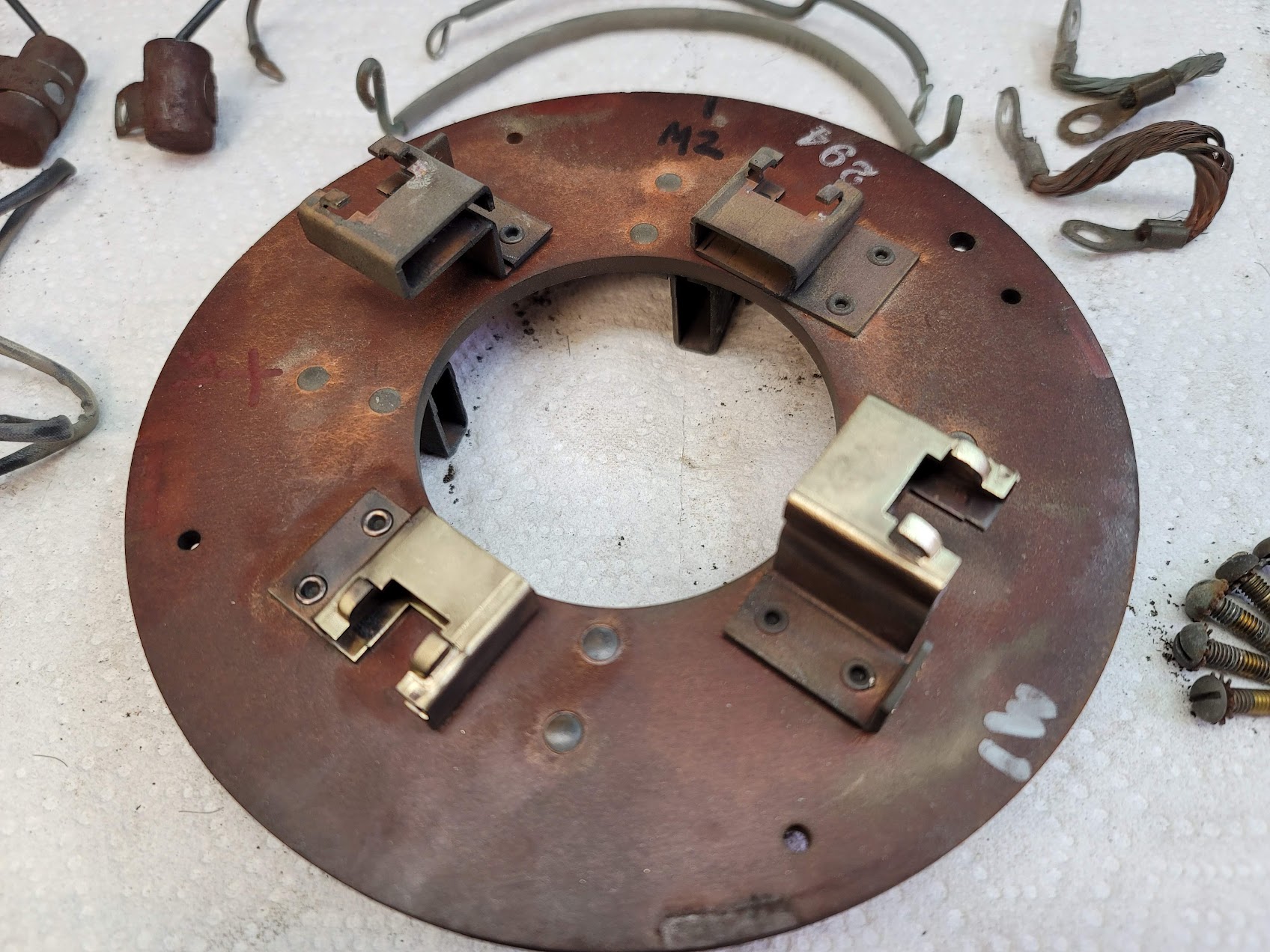
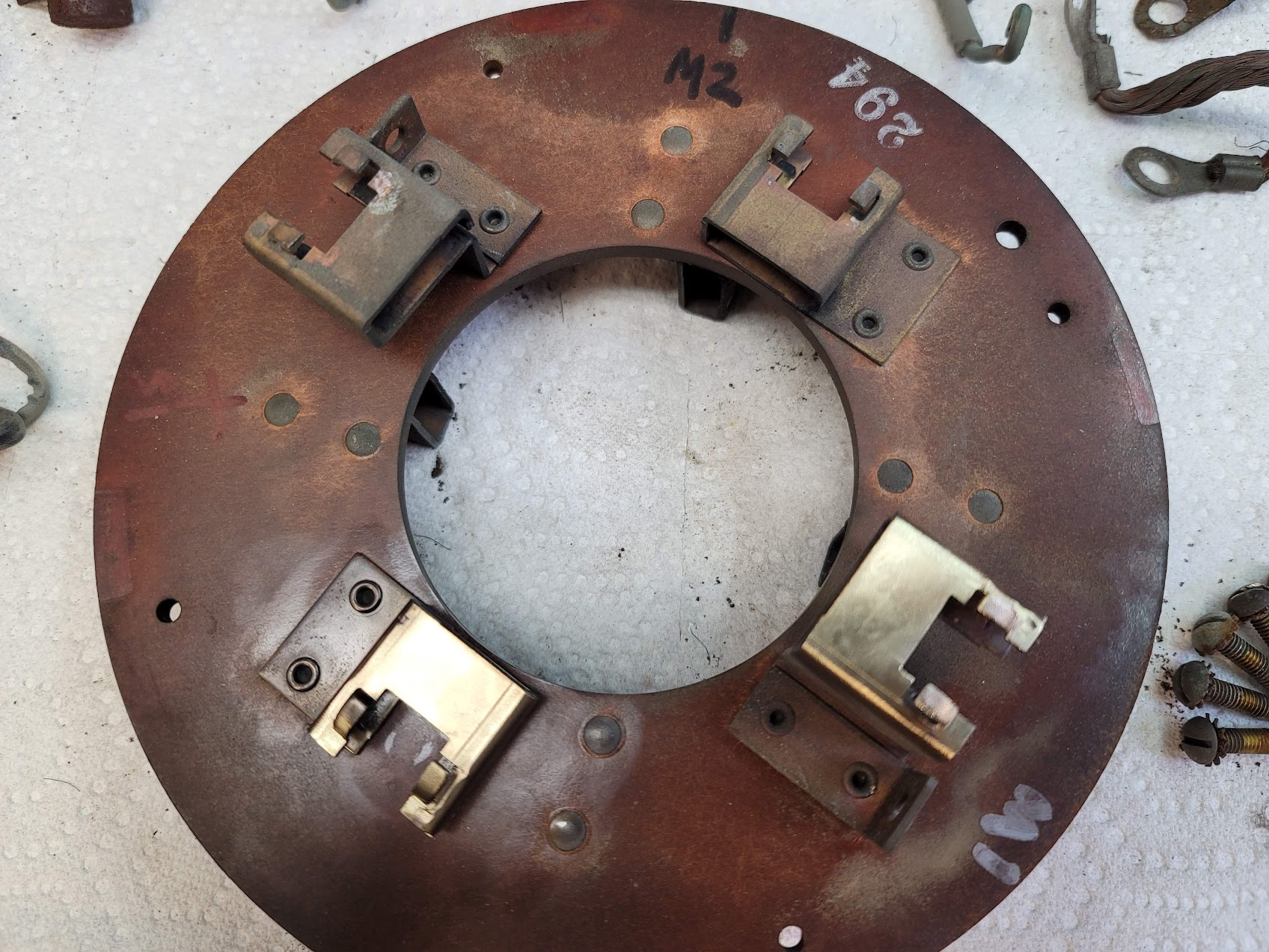
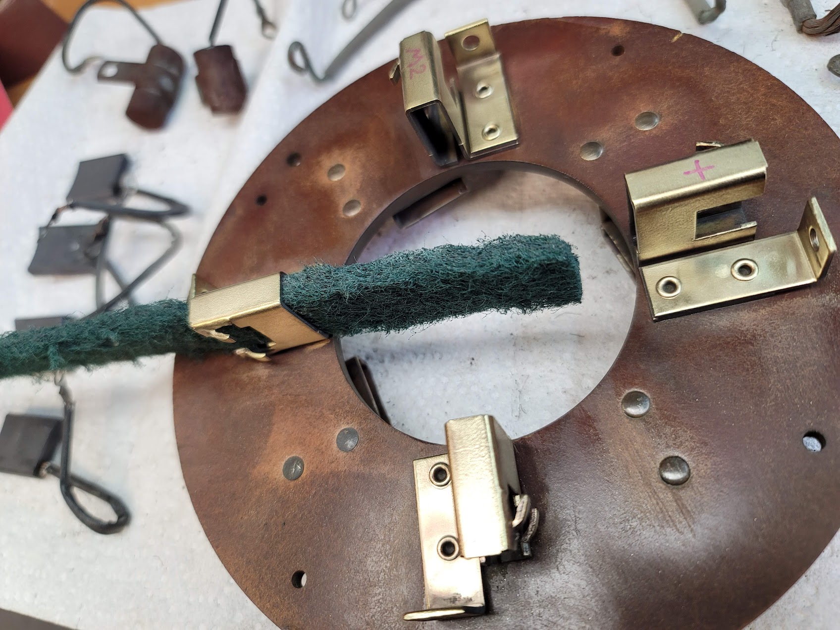
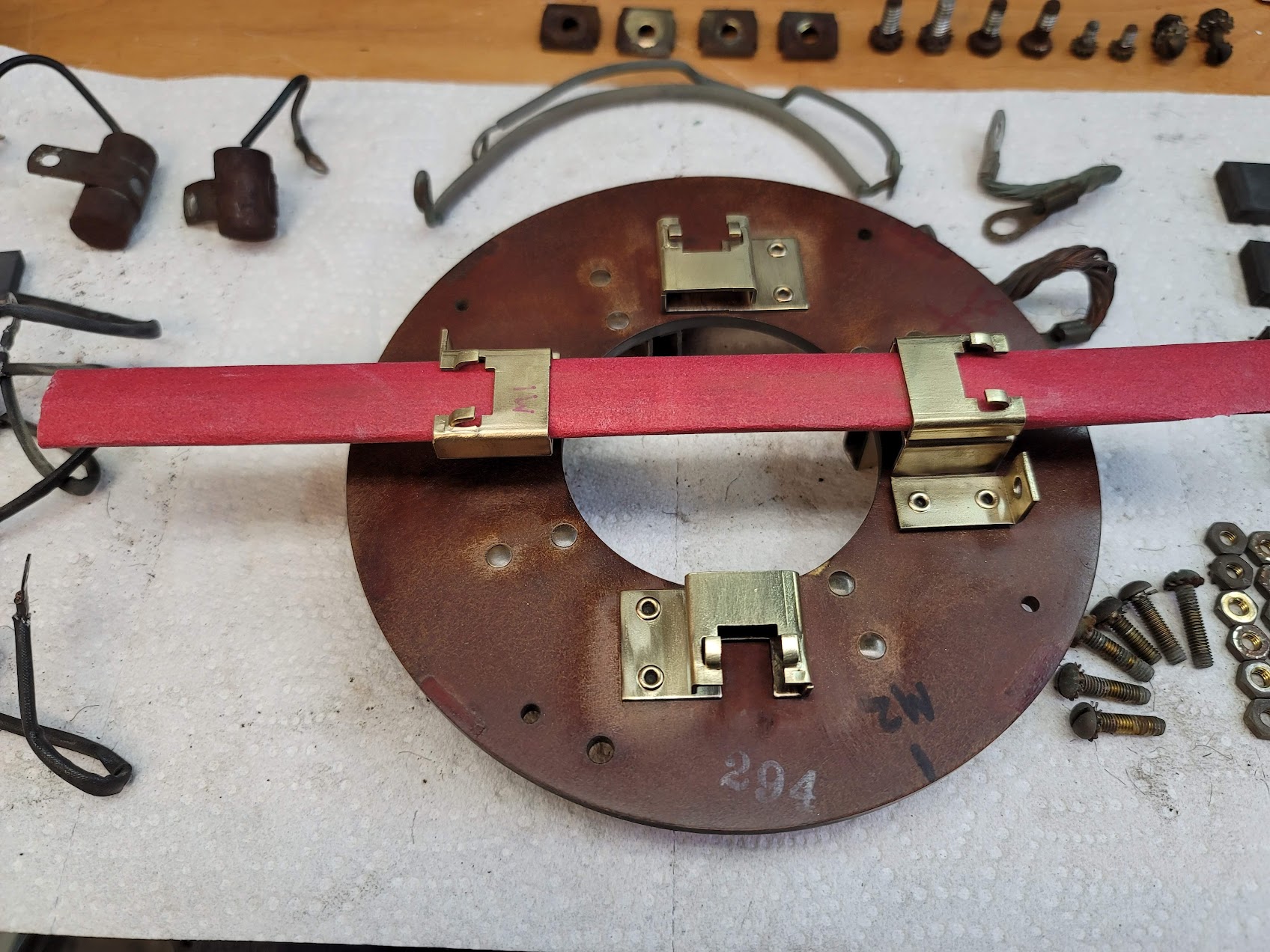
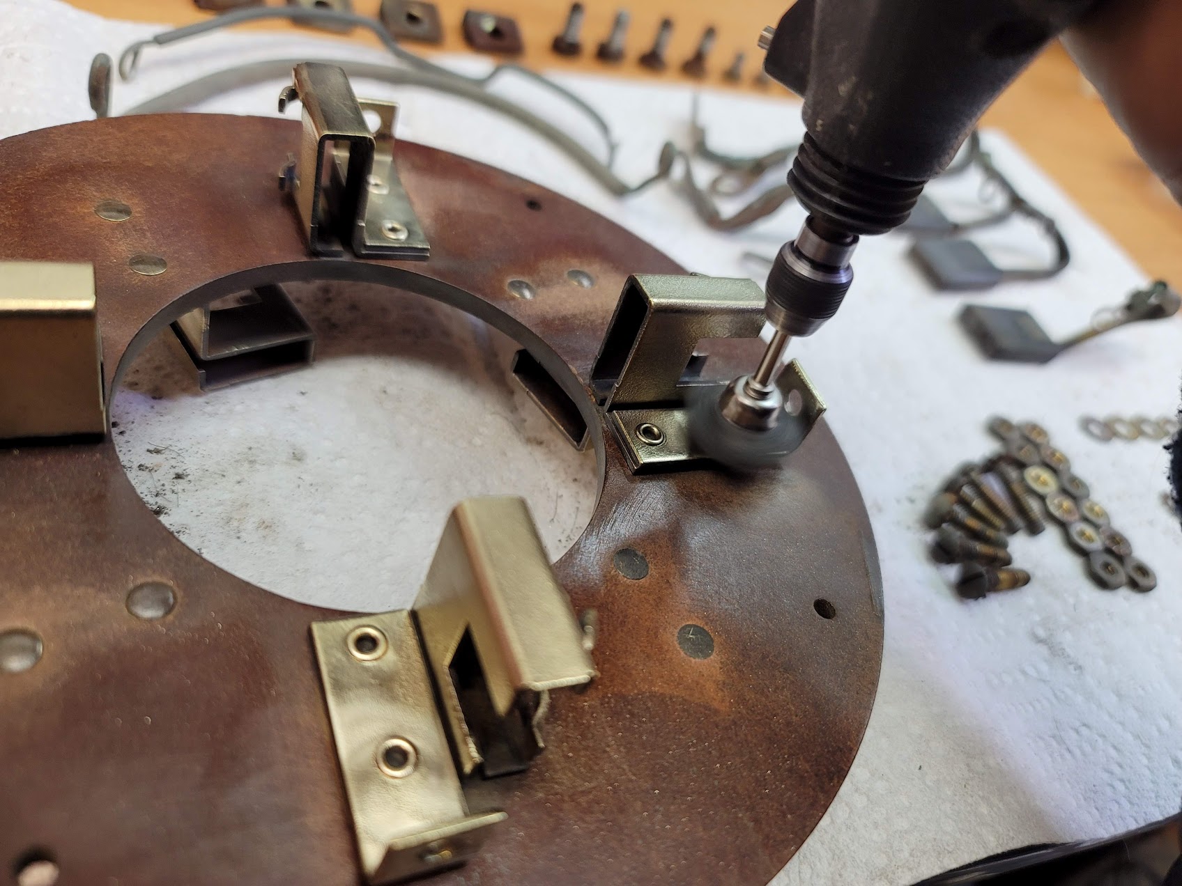
Lots of little hand work, and Dremel work to clean of years of oxidation both inside and out of the brush holders.
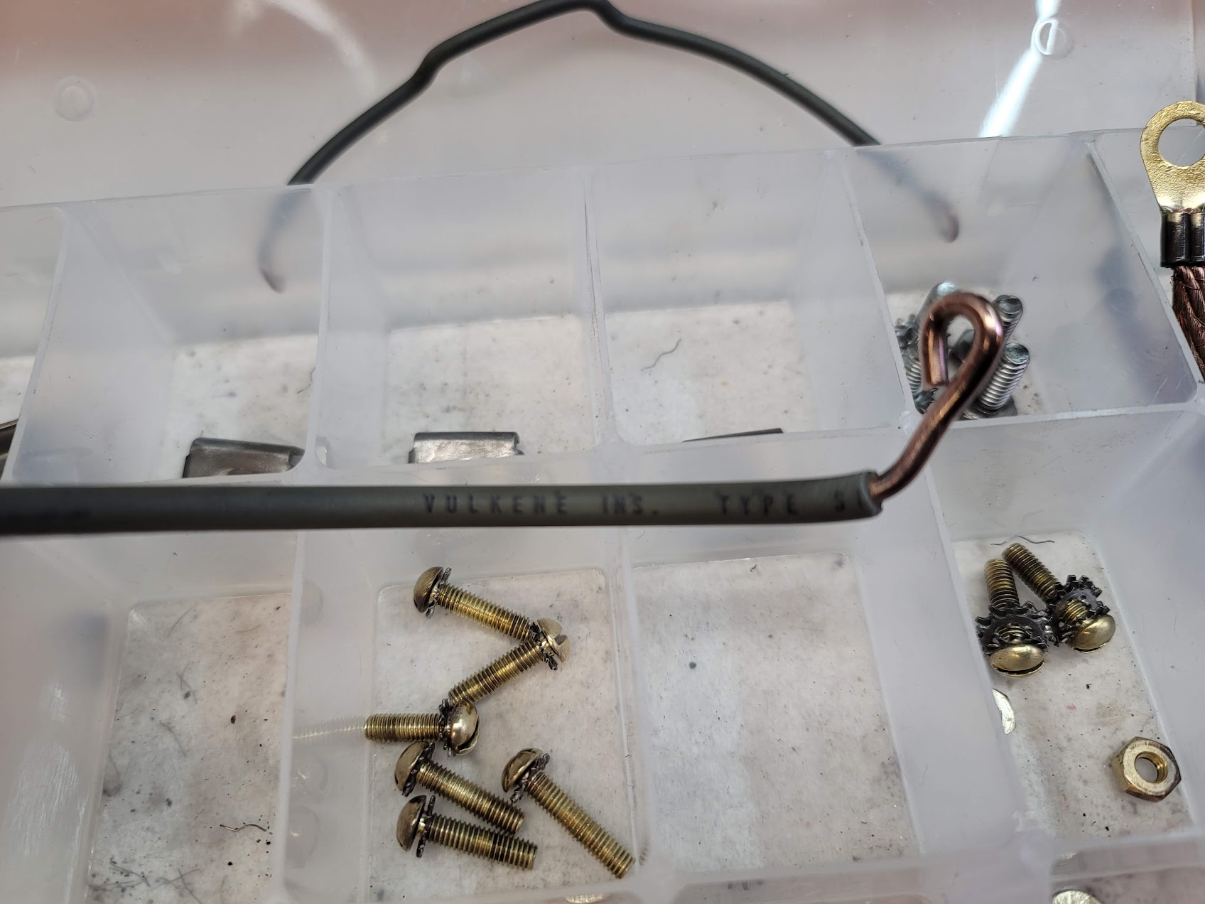
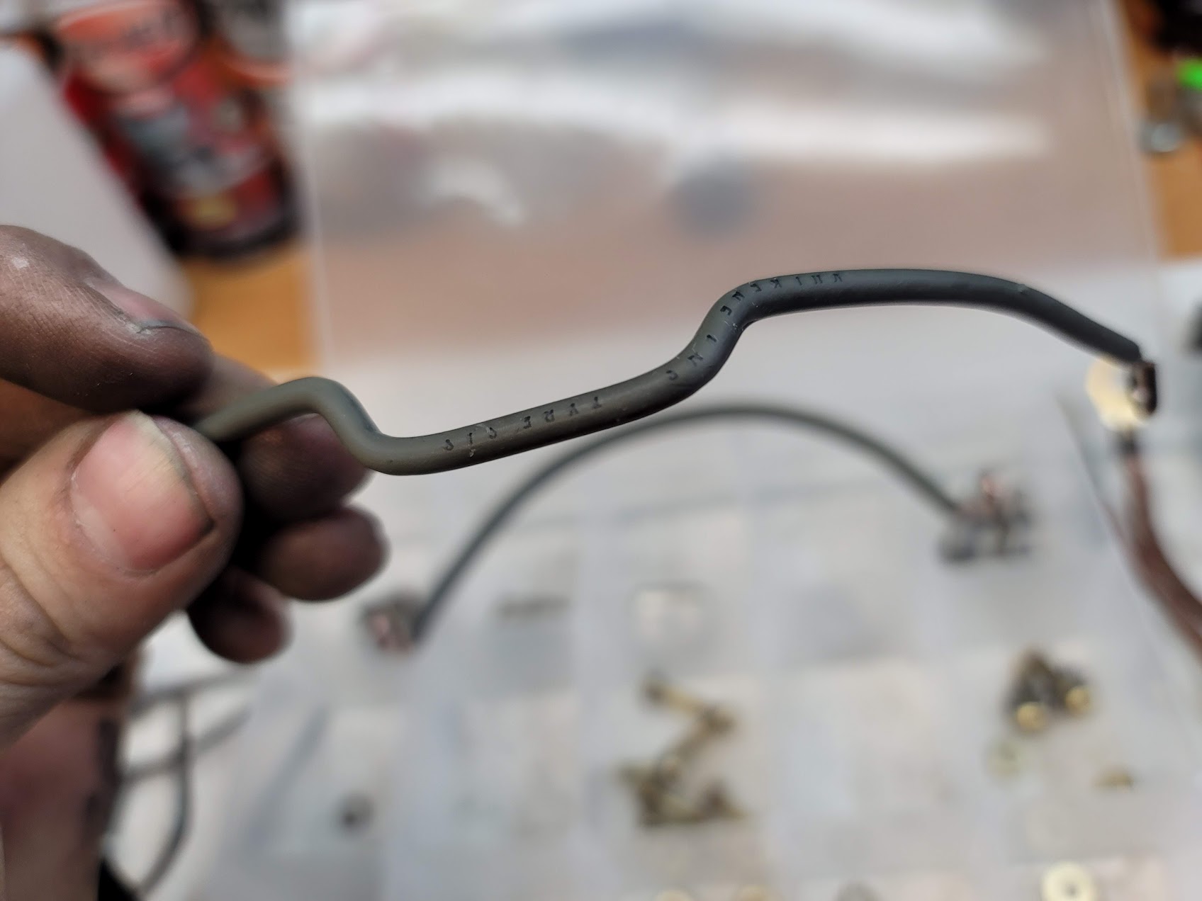
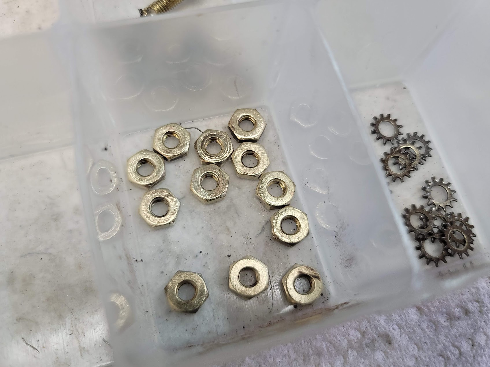
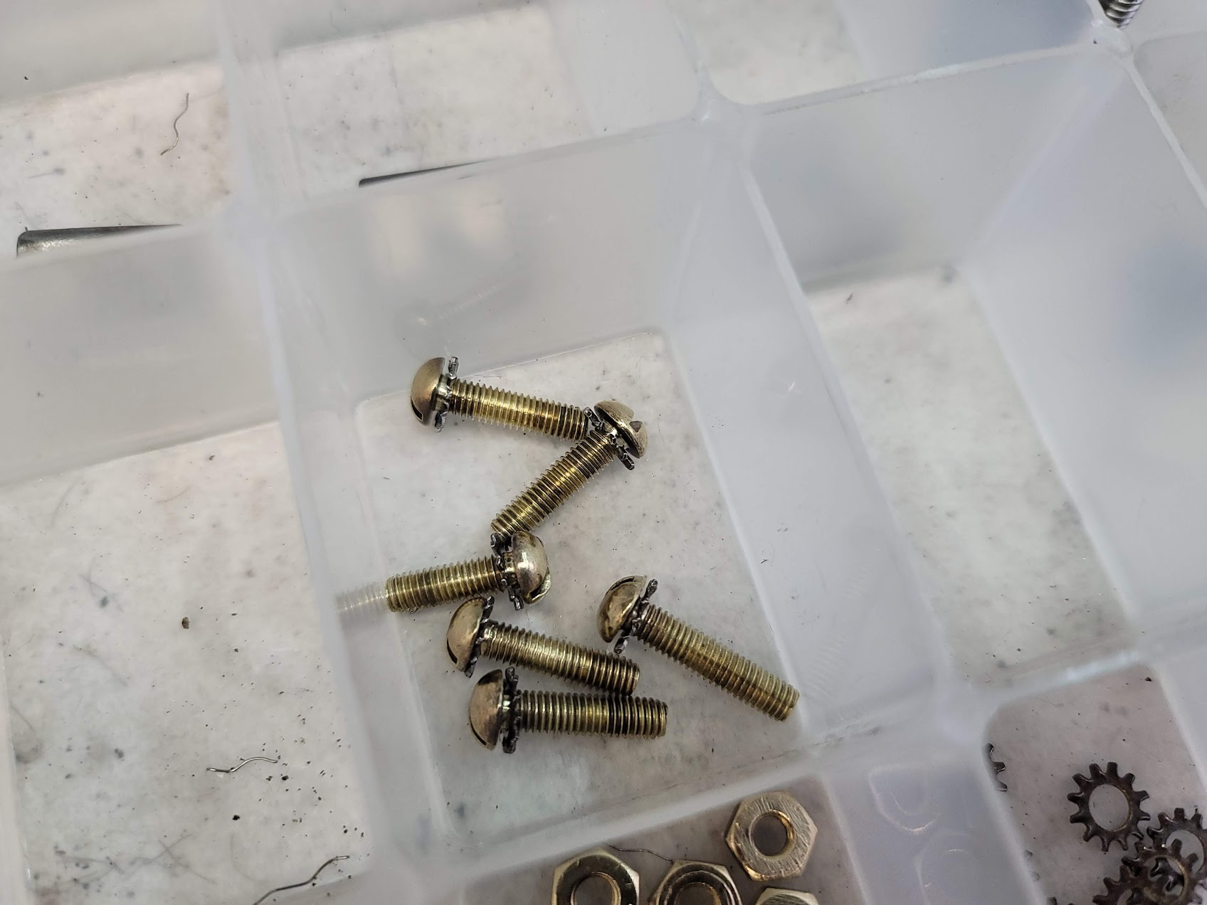
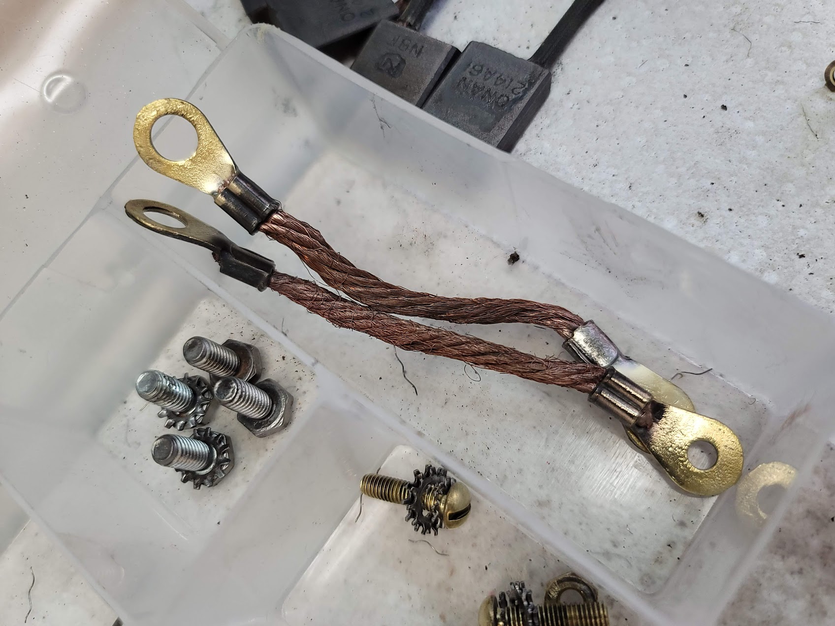
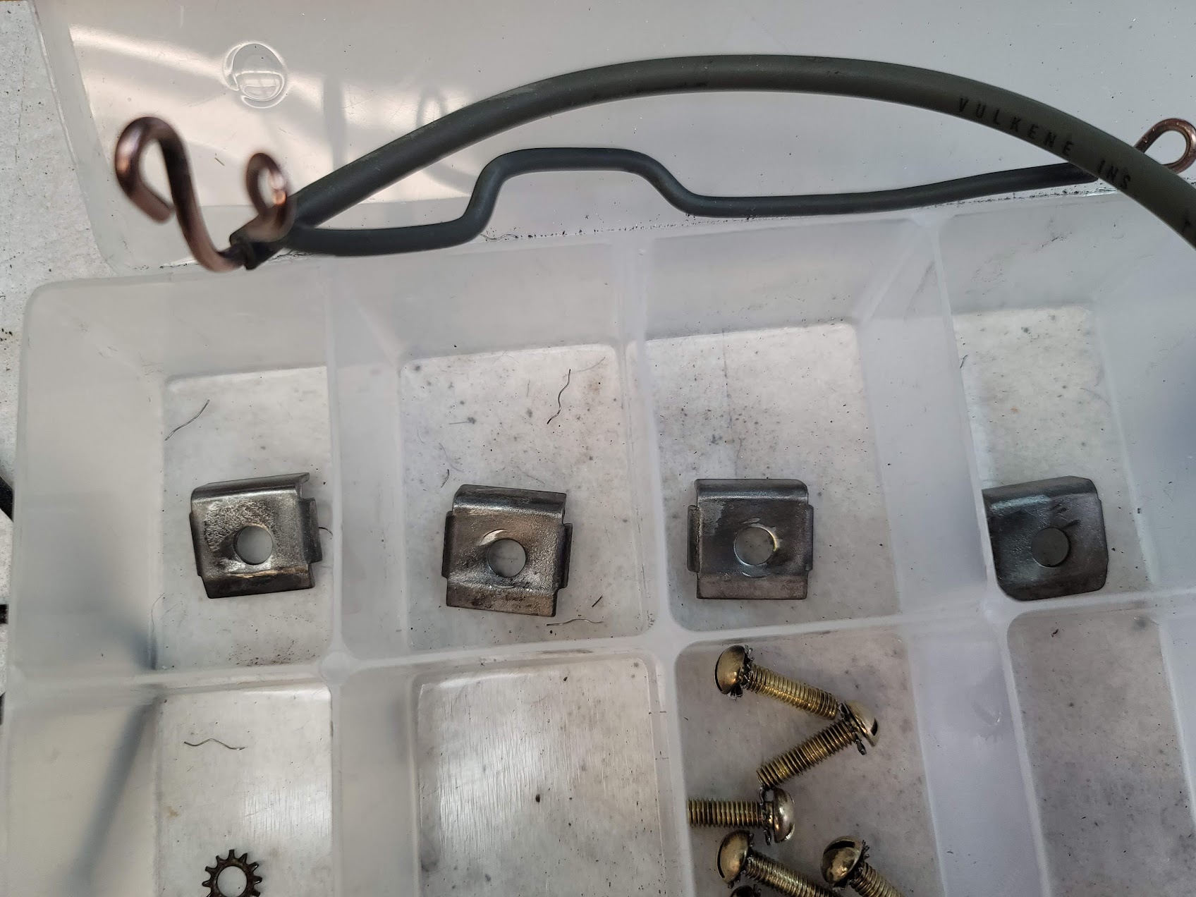
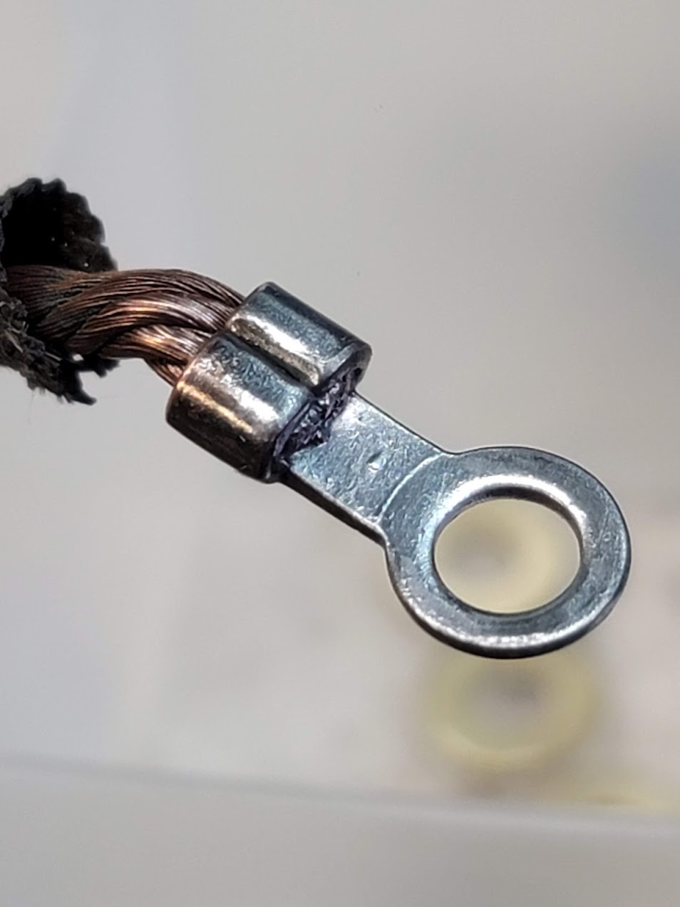
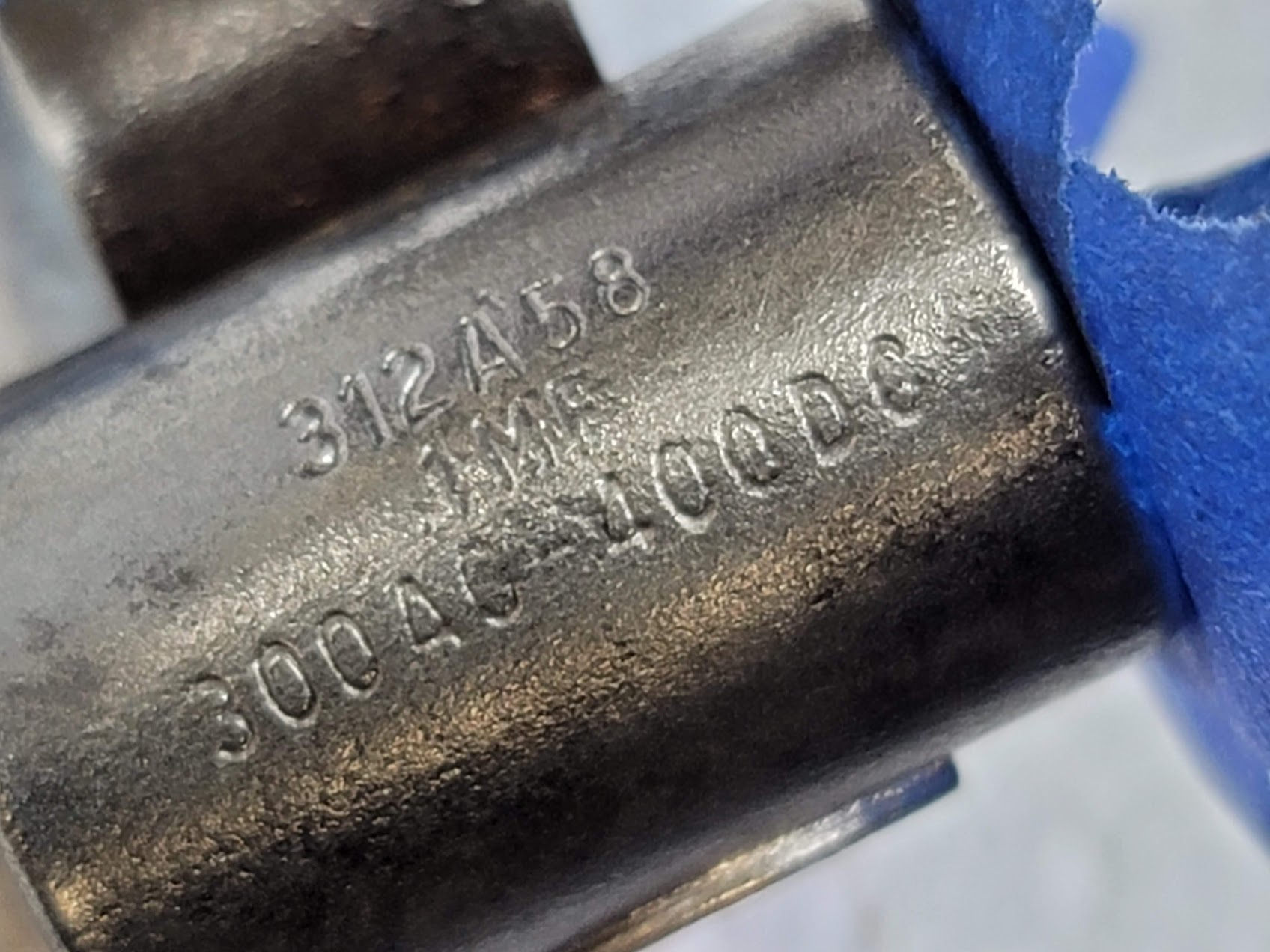
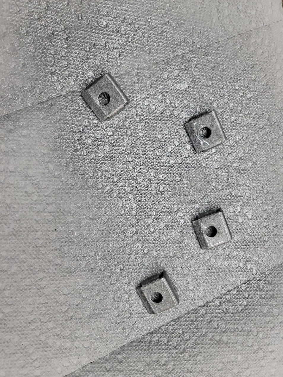
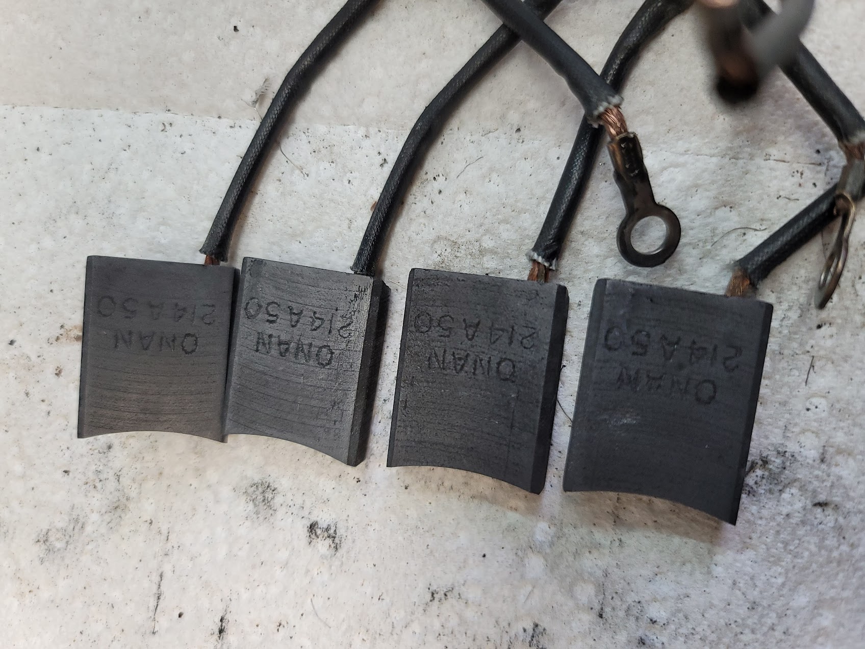
Here is the end result of all the little parts. I hand lapped the brushes to make sure they are clean and true. Lots of little fiddly work on the nuts and bolts, funny how you don’t think about how many sides a nut has!
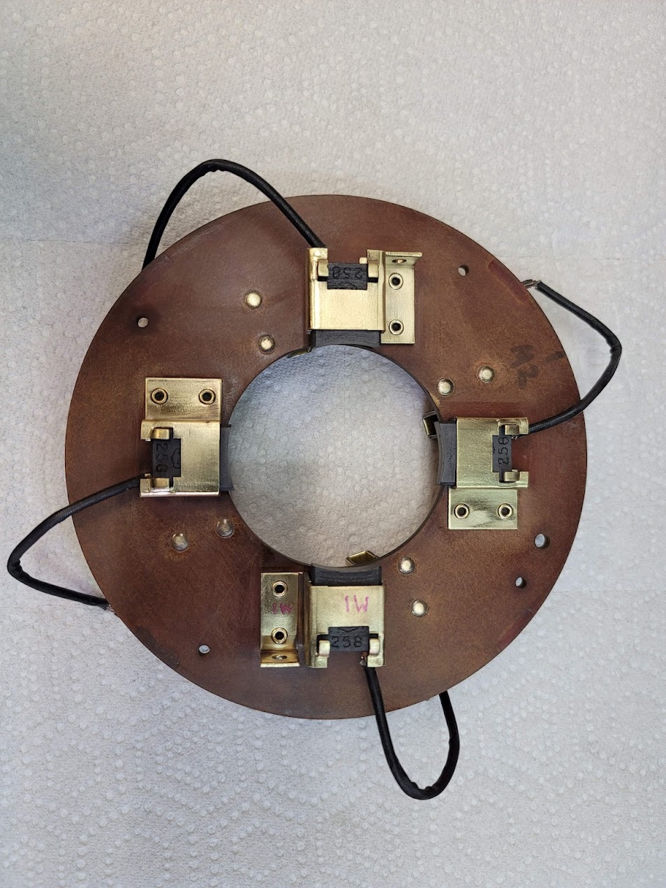
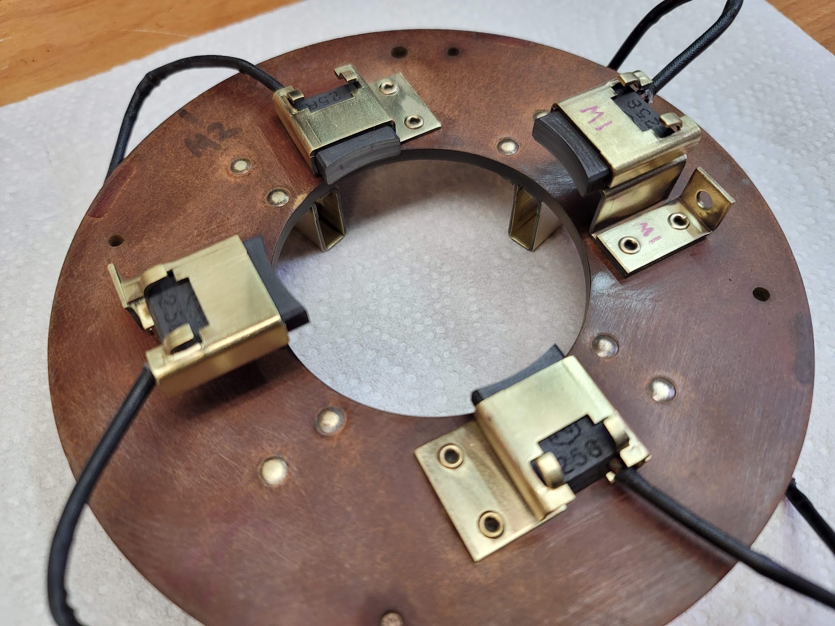

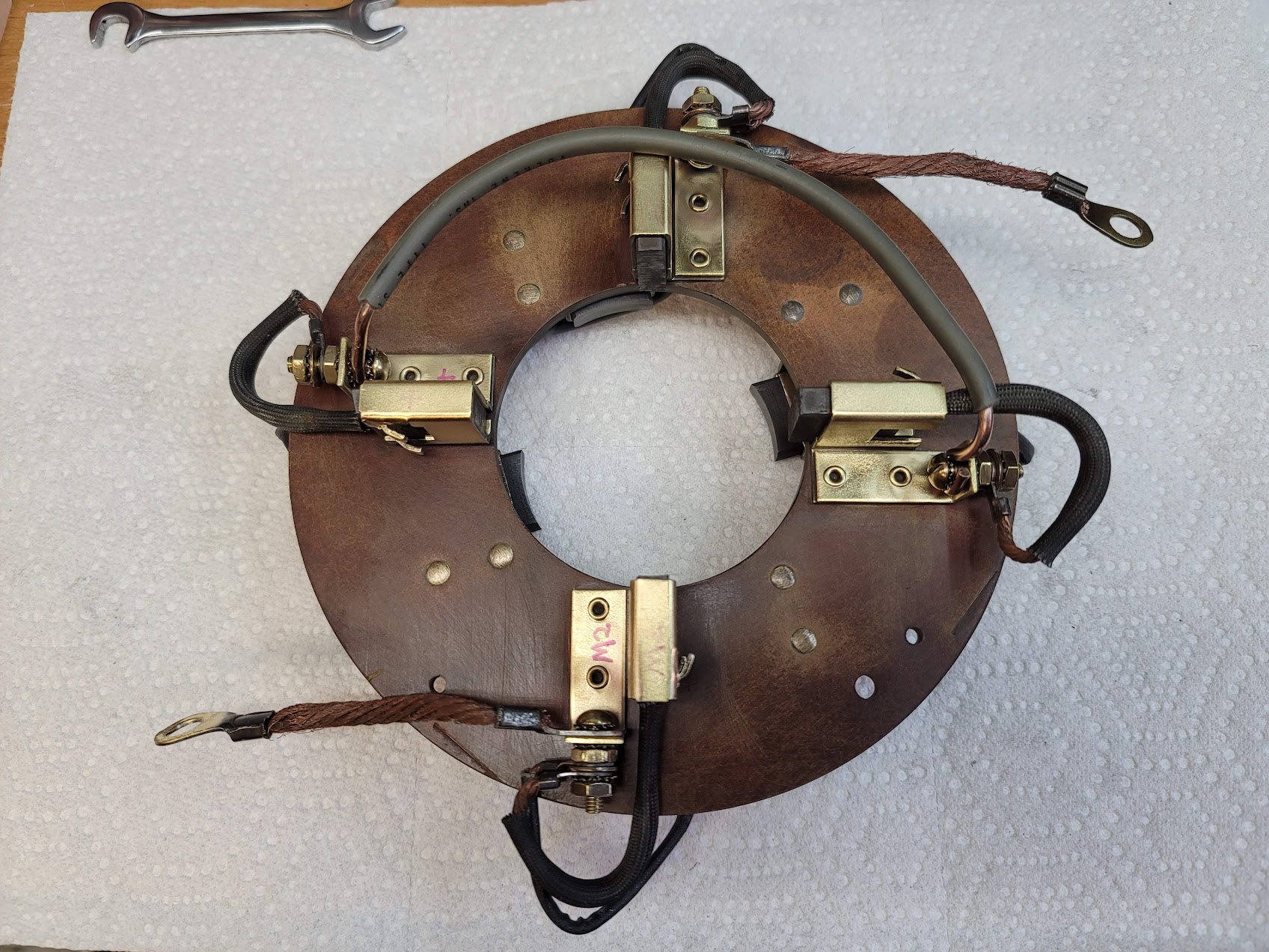
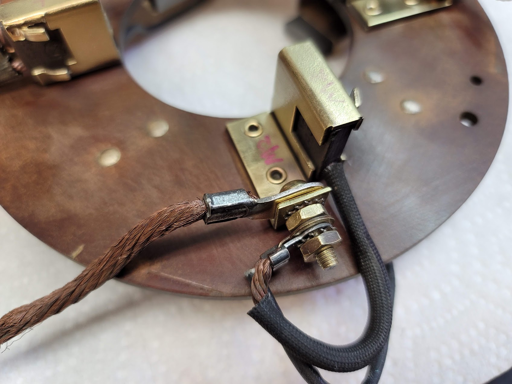
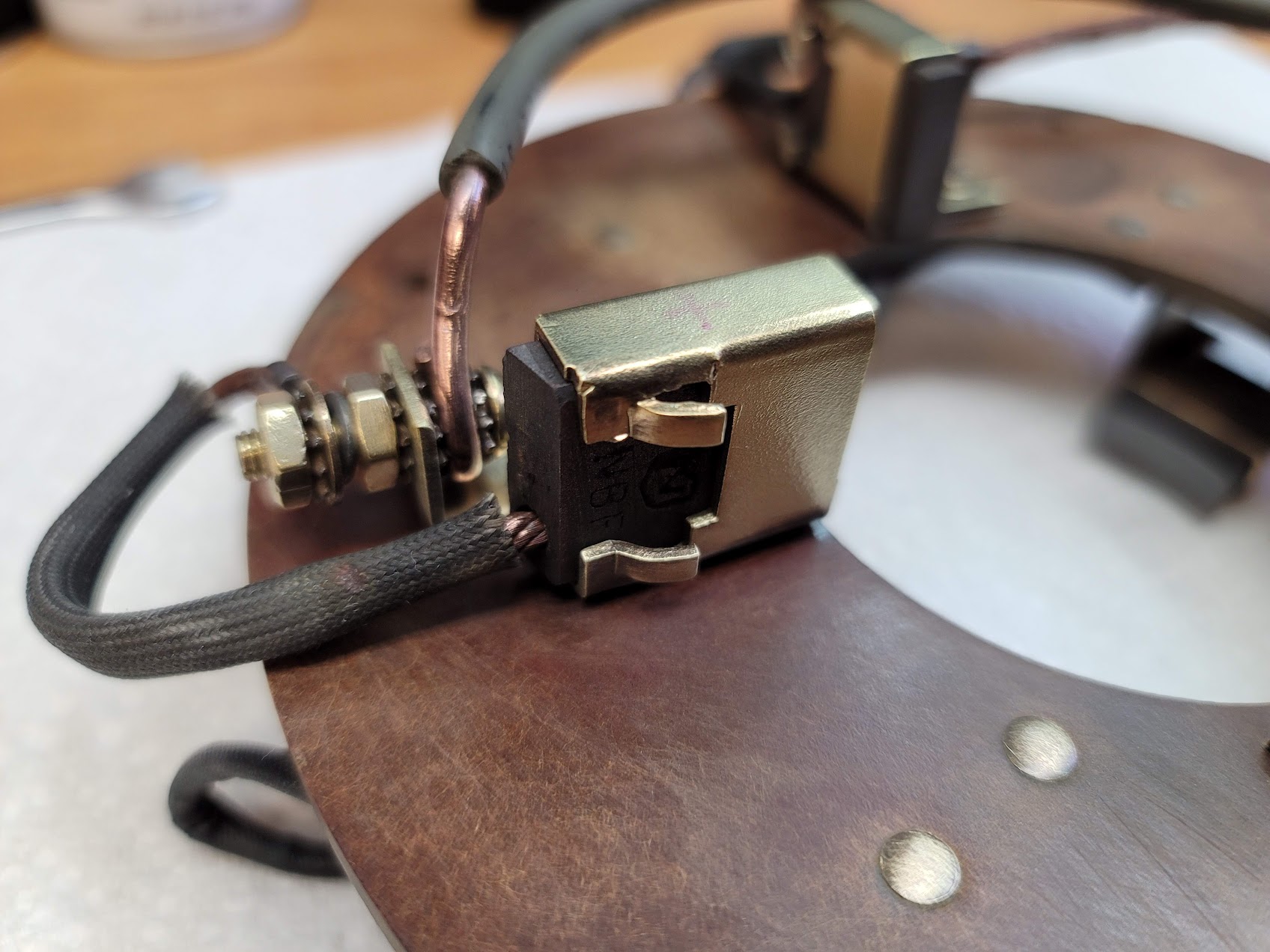
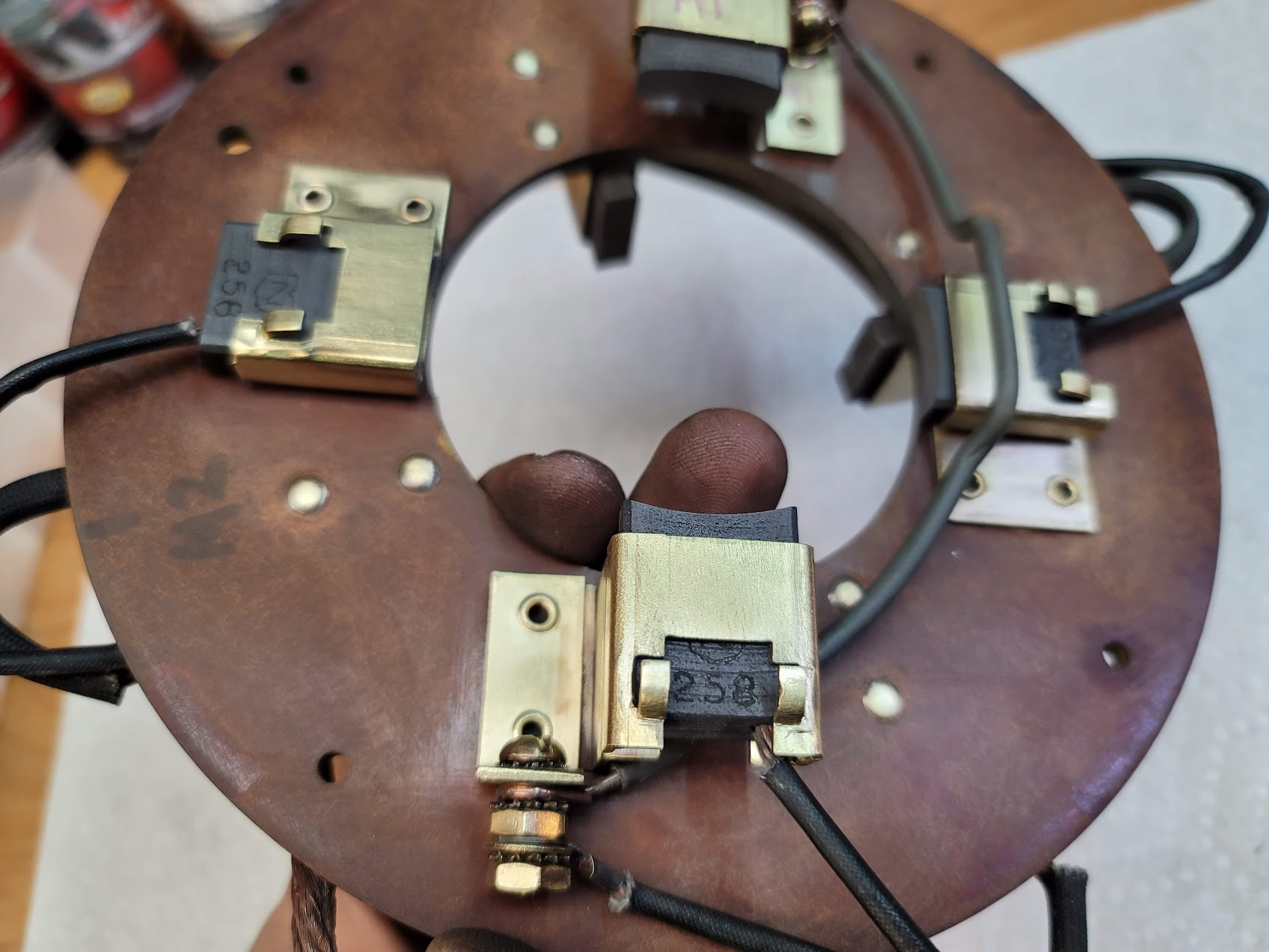
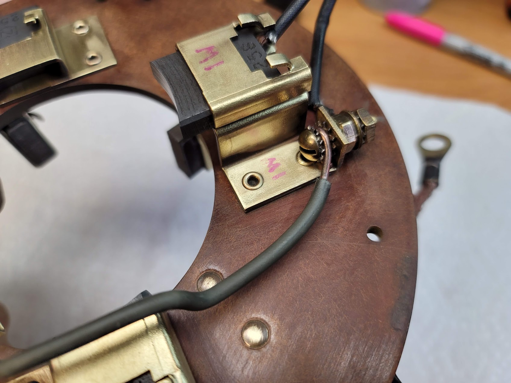
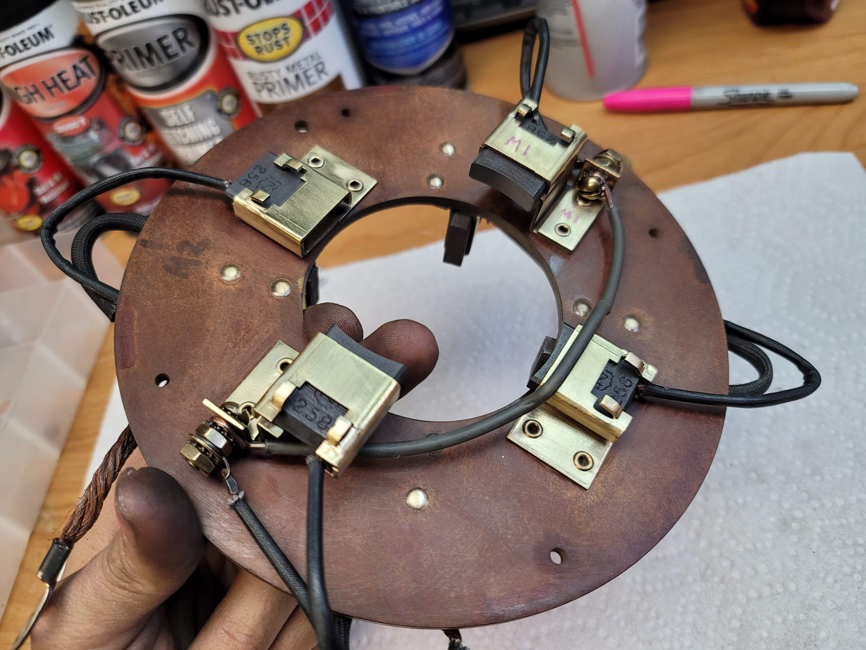
Here it is all done! Looks brand new! Should work and ‘conduct’ much better now as well, far less resistance.
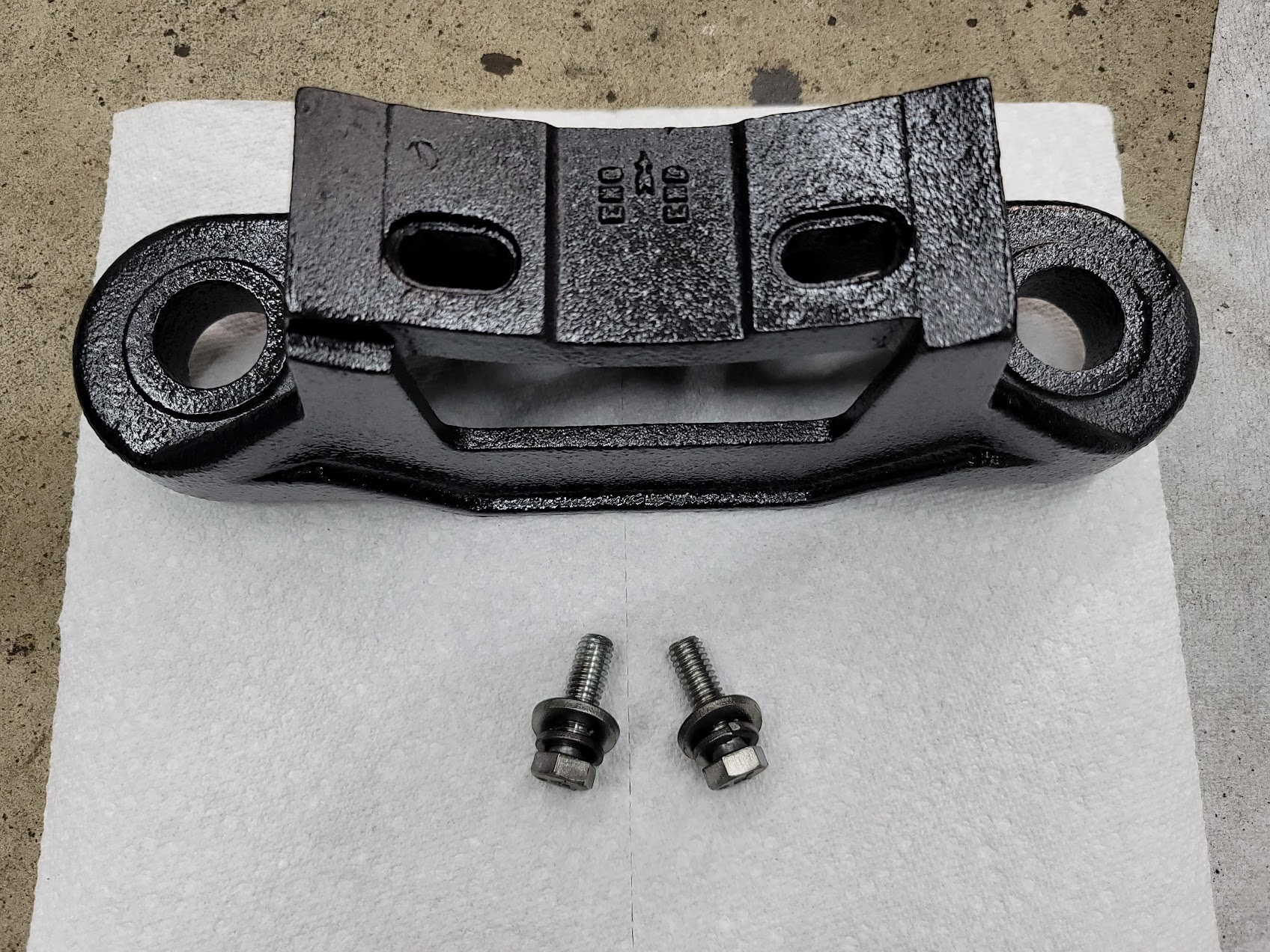
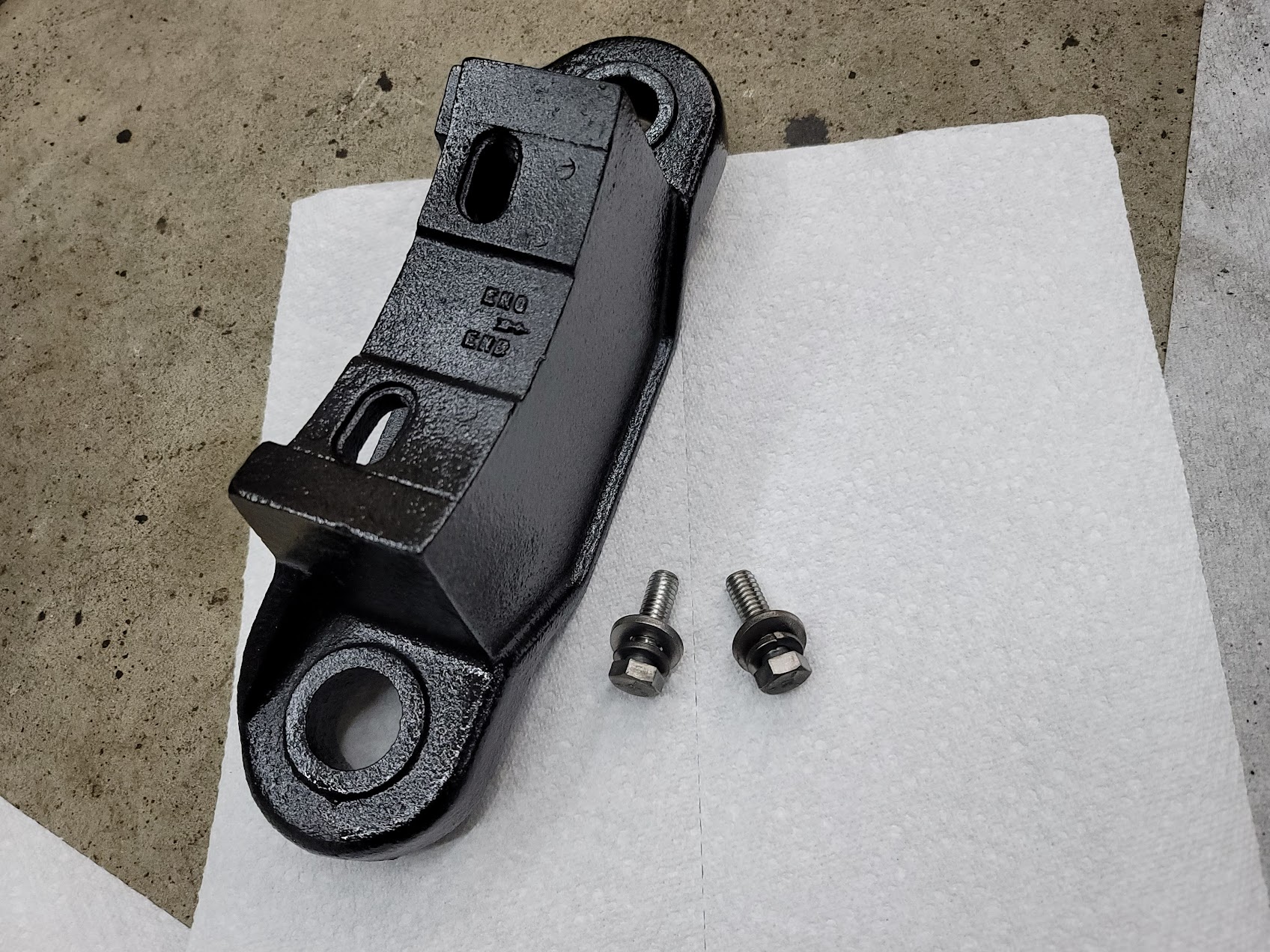
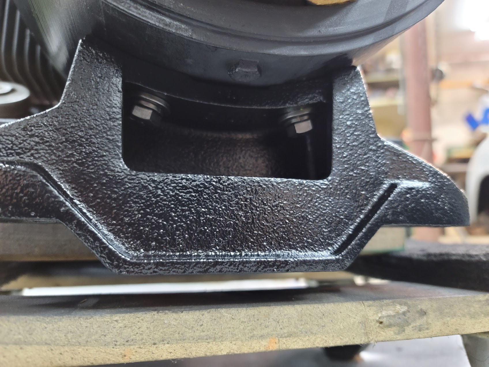
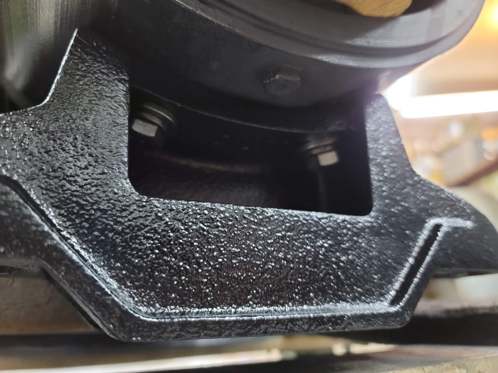
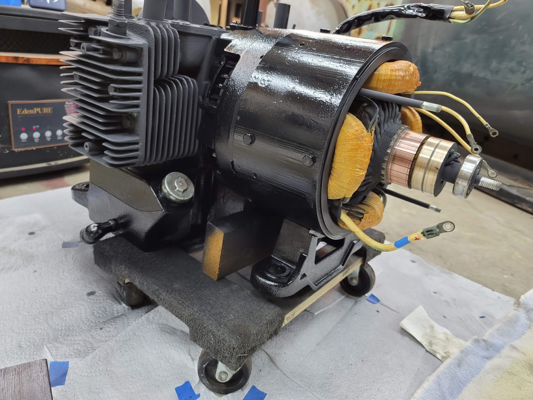
Next project was to finish getting the freshly refinished foot and bolts mounted back up to the motor.
Here is what it started out looking like,
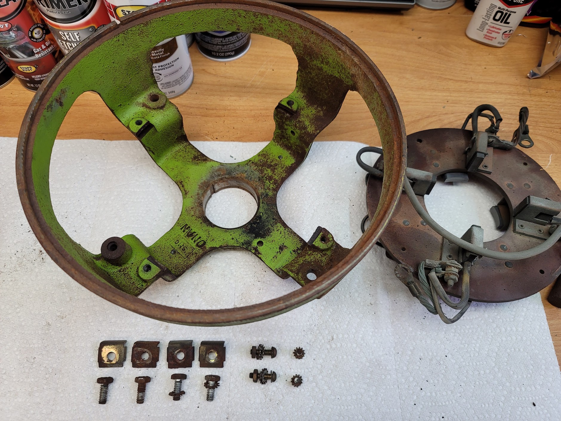
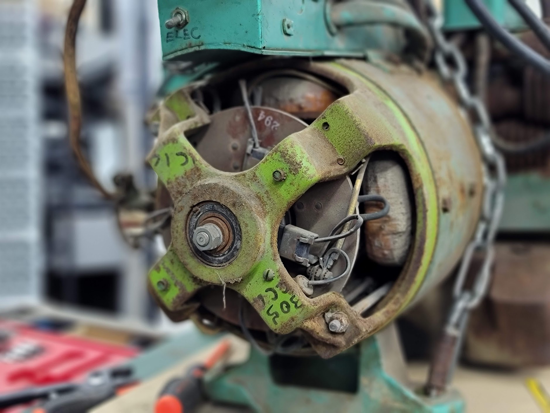
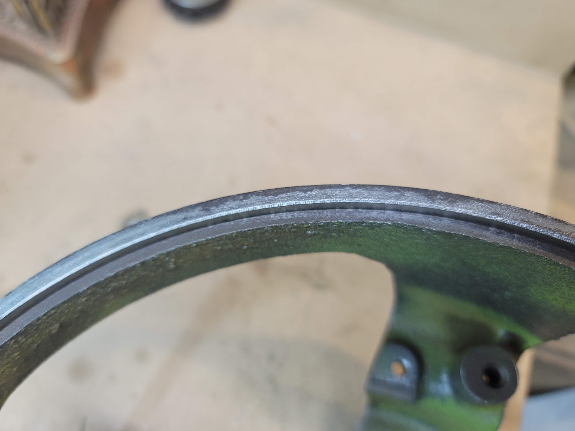

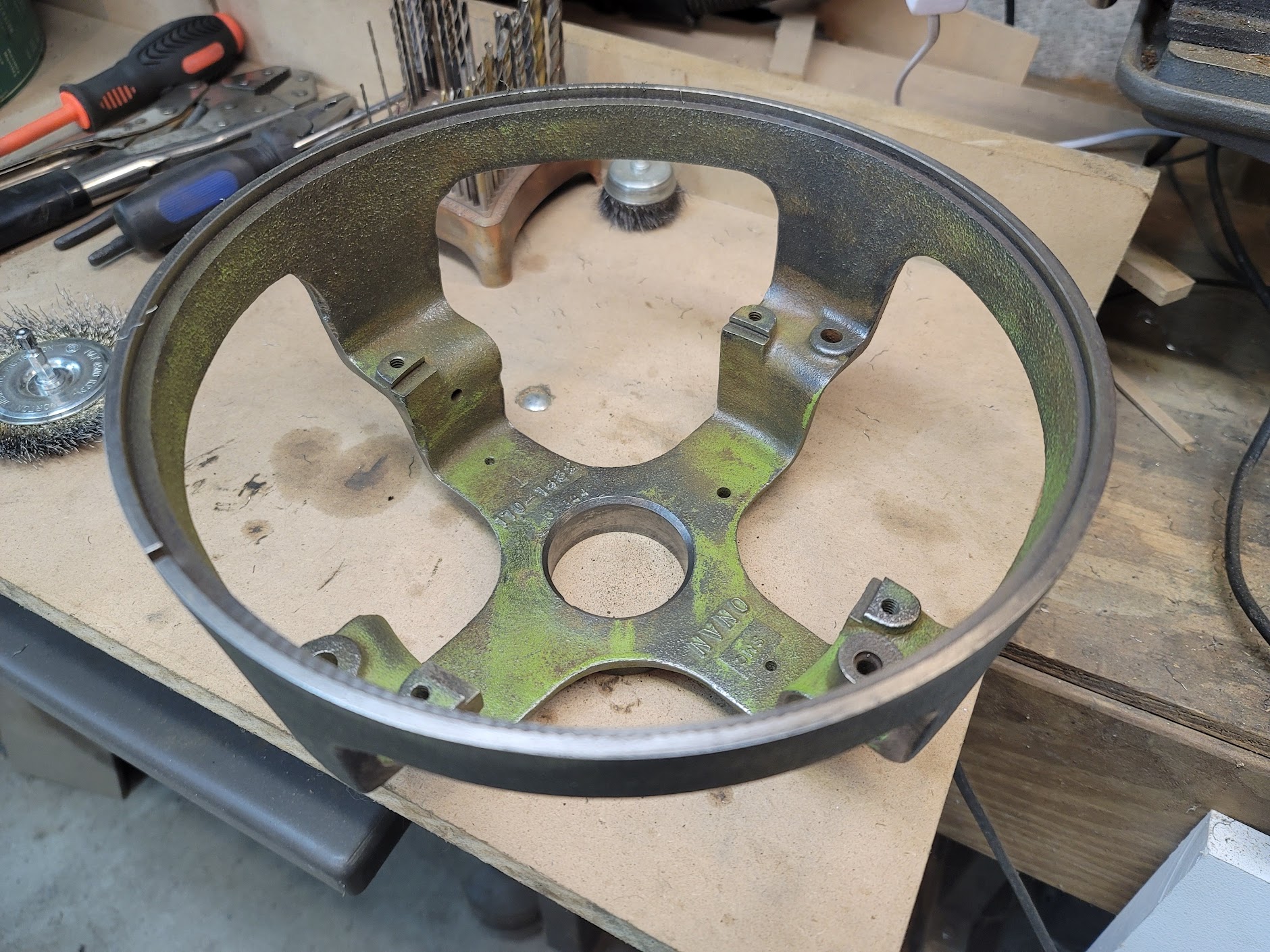
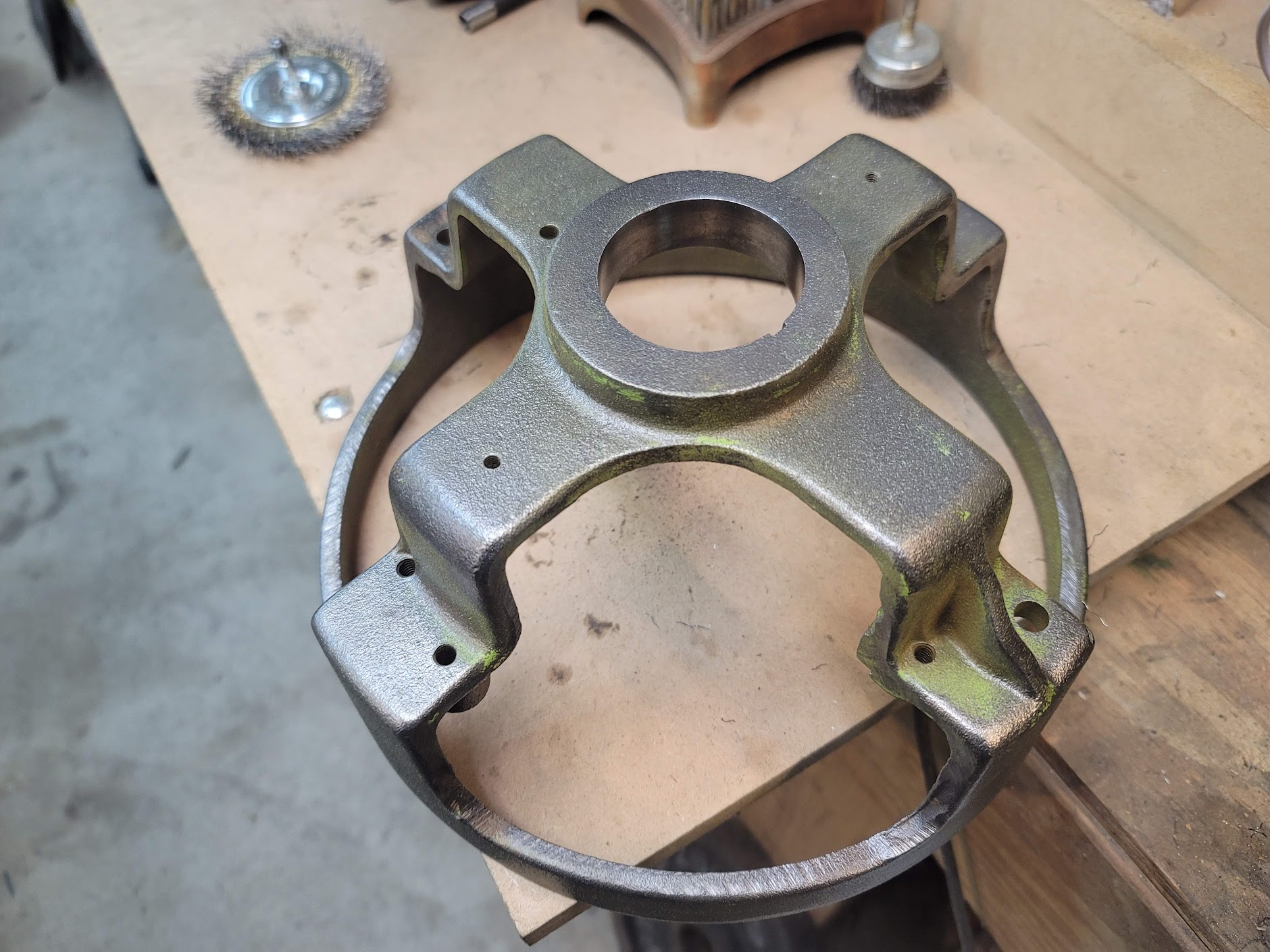
Hours at the wire wheel got me this far.
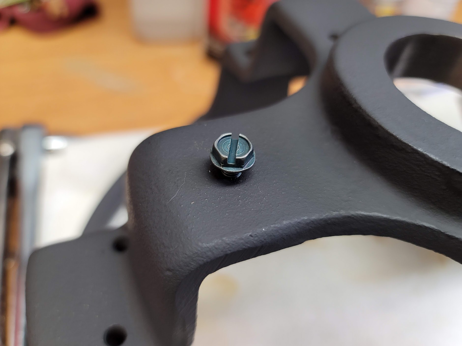
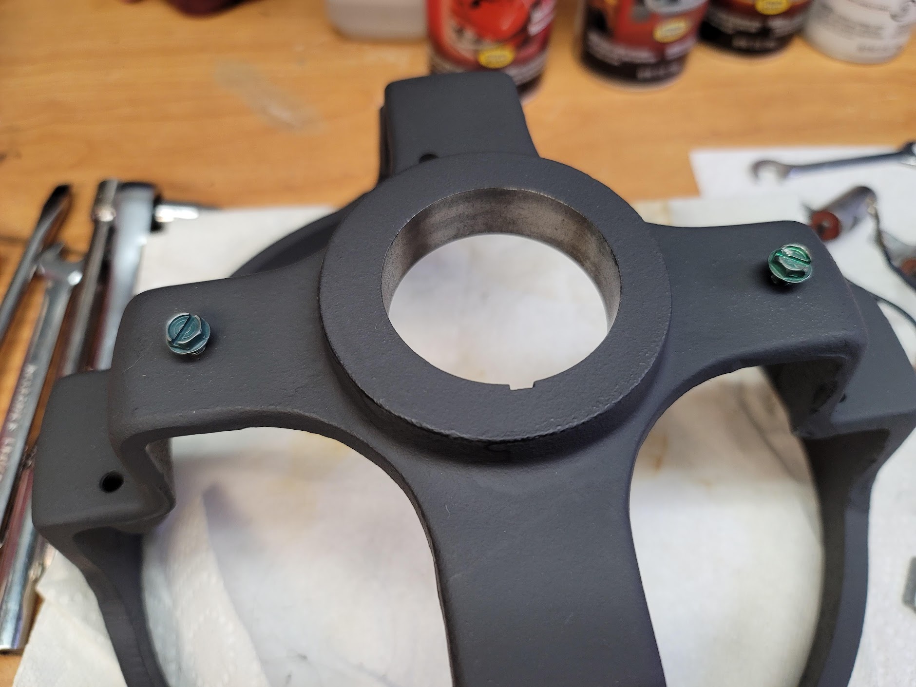
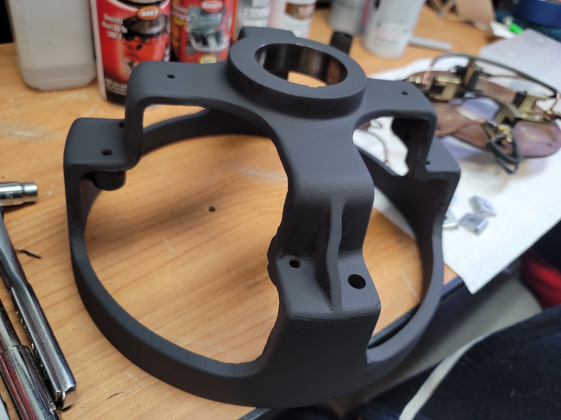
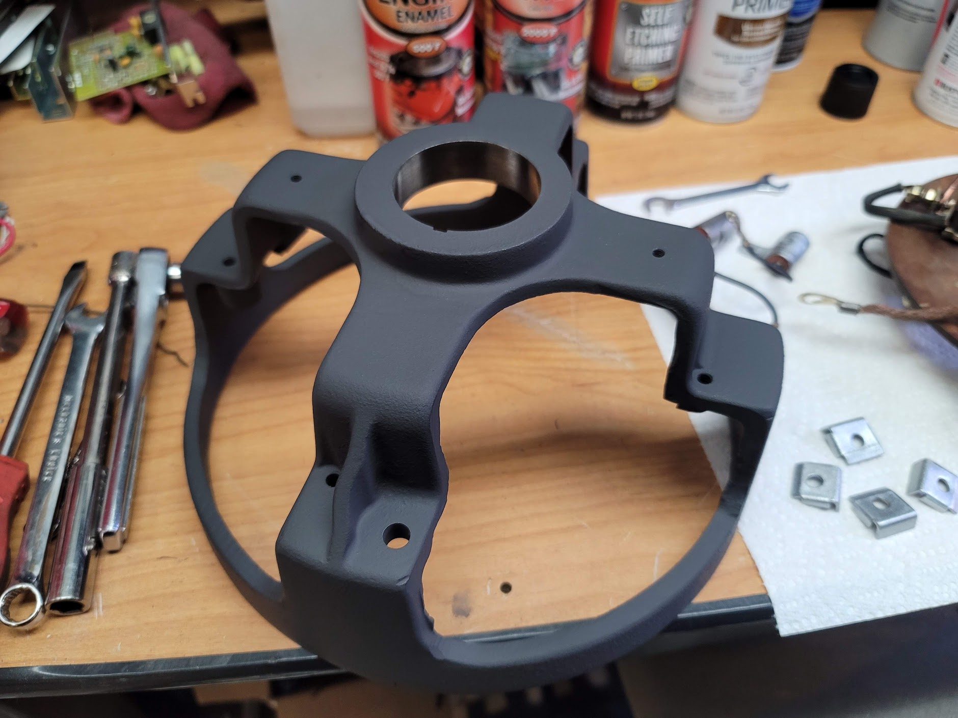
Forgot to get a finished pic before paint, but it now has a coat of flat on it. I found some new back cover screws. Used some vintage ground lug screws. Seemed fitting.
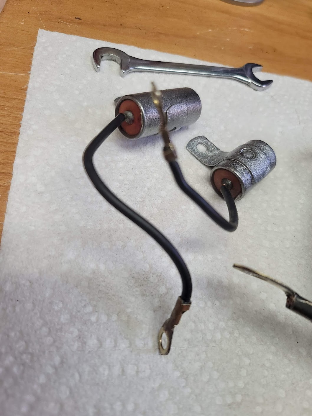
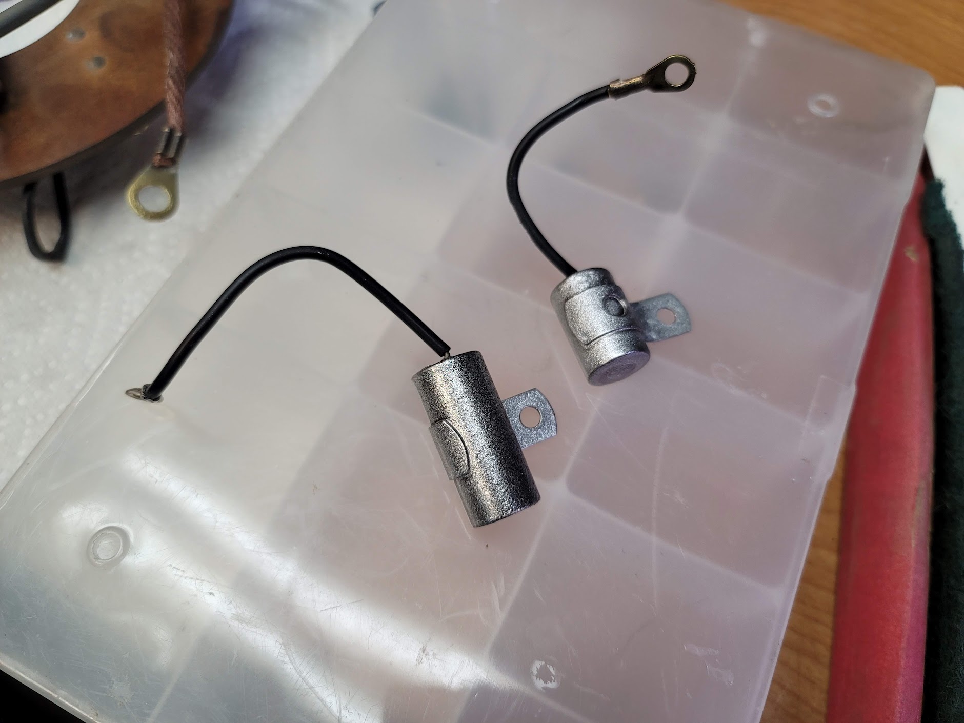
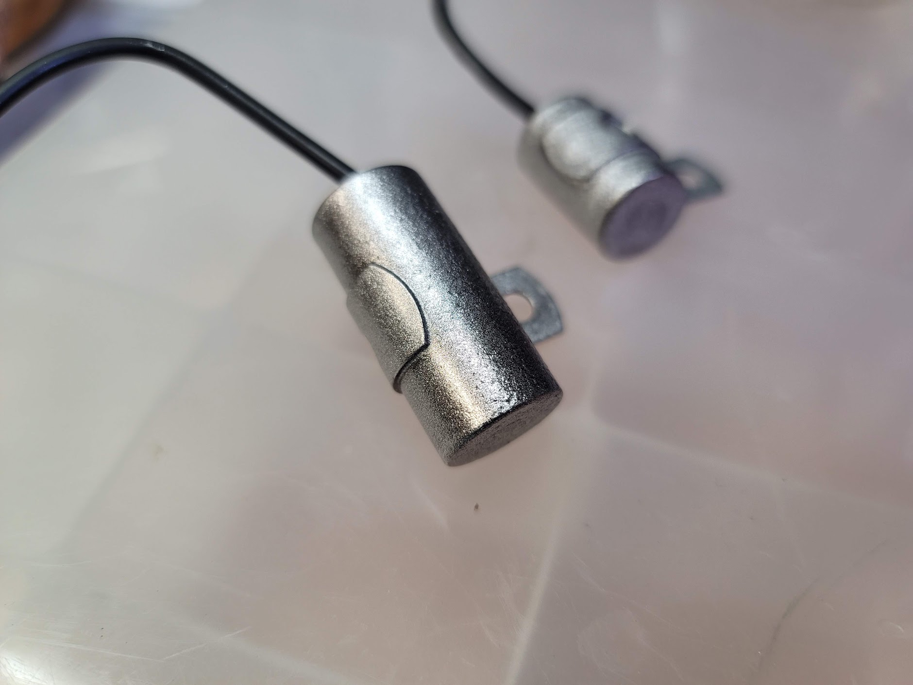
Refinished the condensers, or AC noise suppressors. They tested good, but may replace them with modern ones, for these when they fail go with a bang!
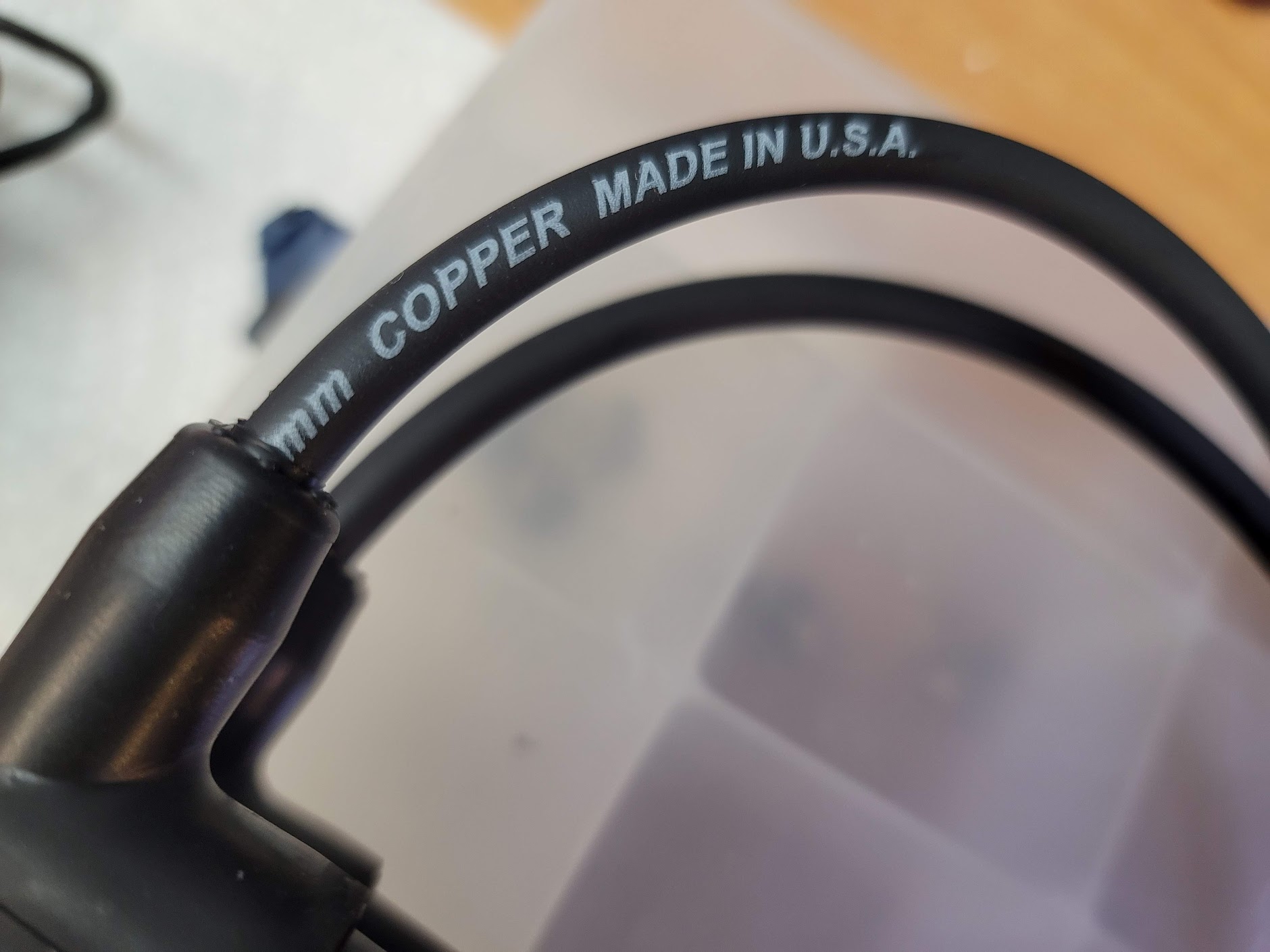
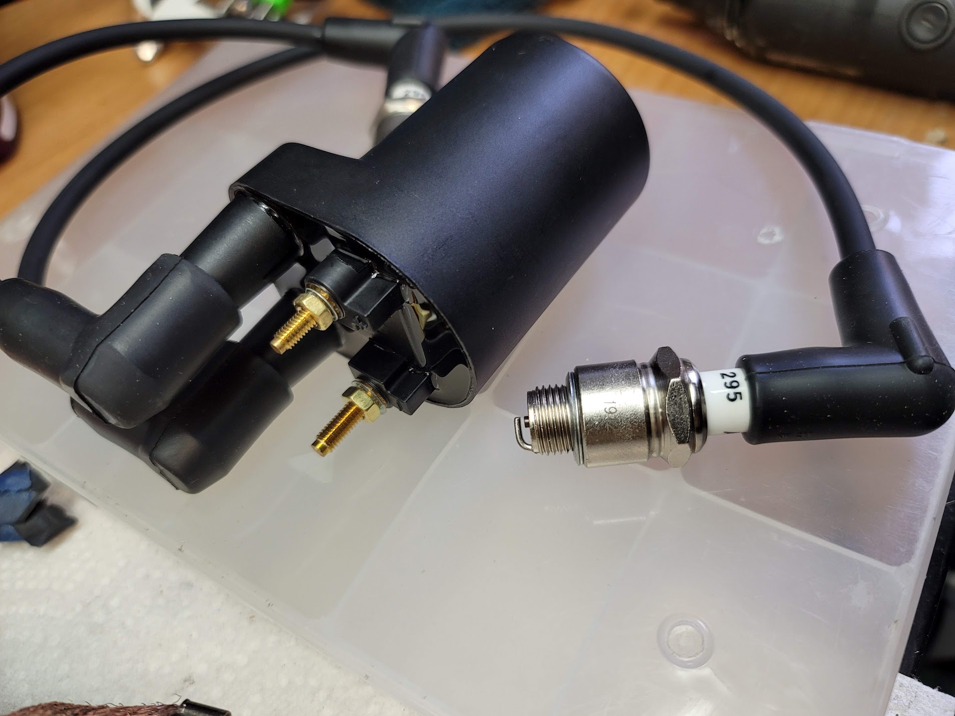
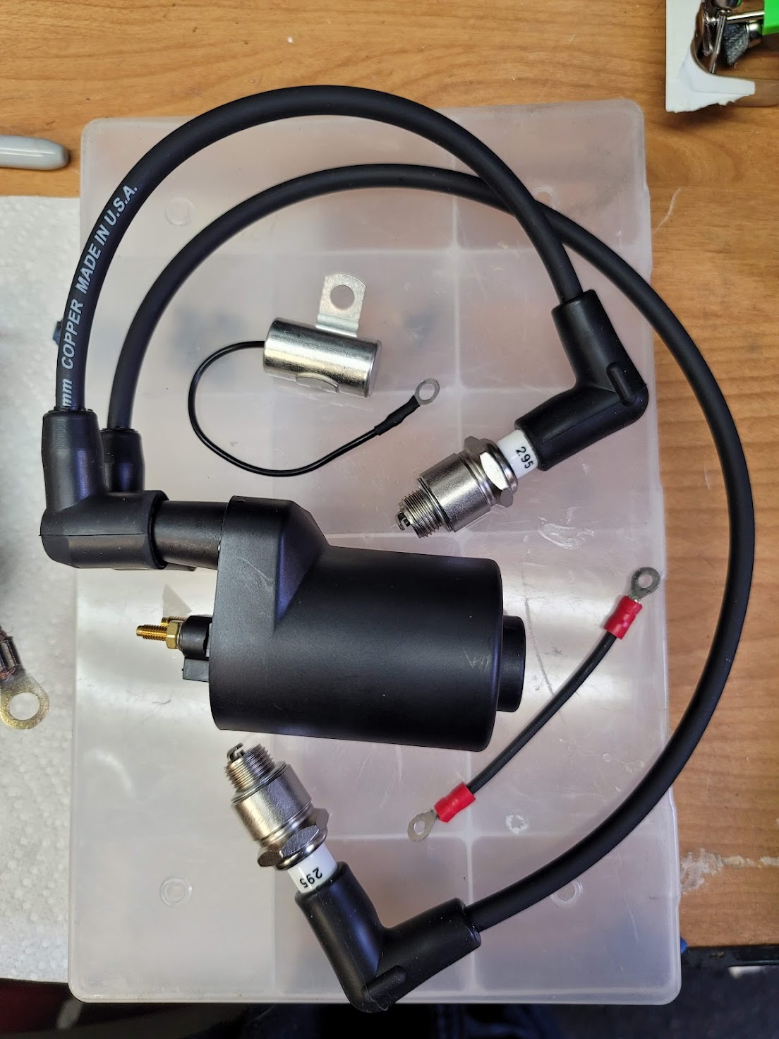
All the parts for the ignition system came in! Now to see if they fit! That will be up next, stay tuned!
UPDATE: 1/28/2022 After cleaning and inspection, the rear bearing was within tolerance and just needed repacked.
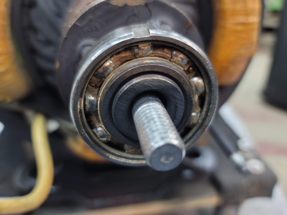
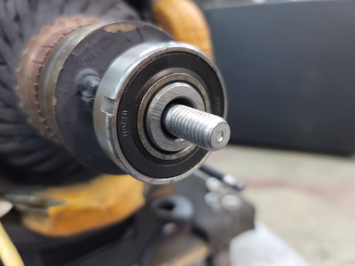
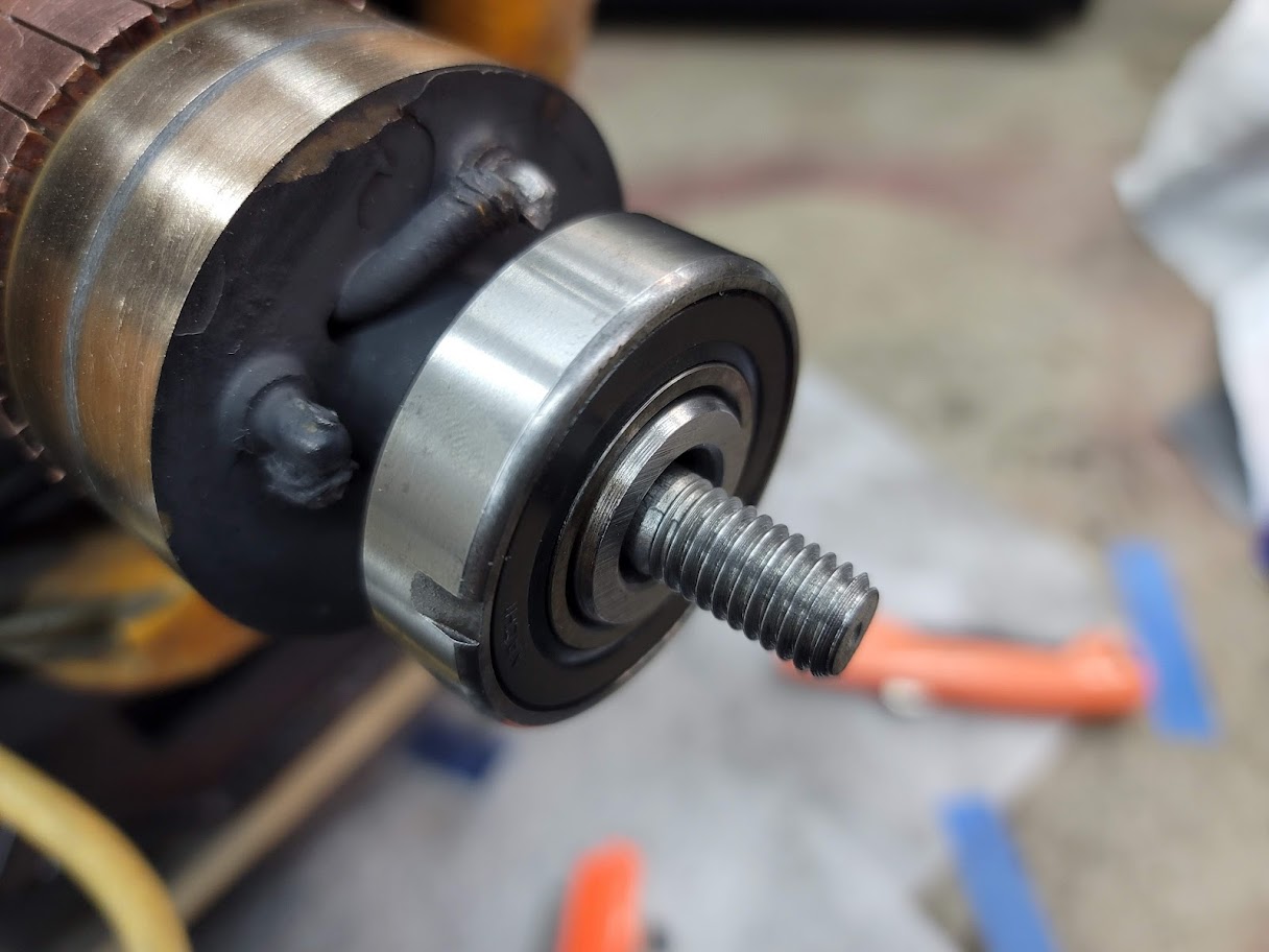
After a removal of old dried up grease and a repack of new, she spins great with no noise or chatter!
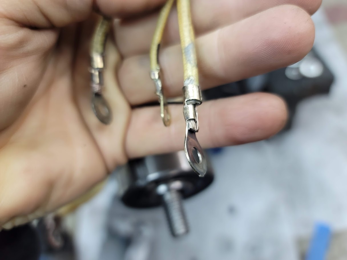
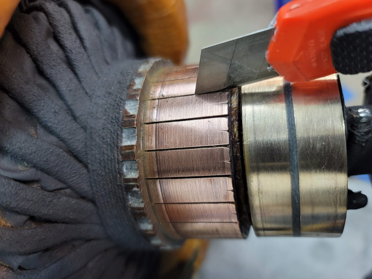
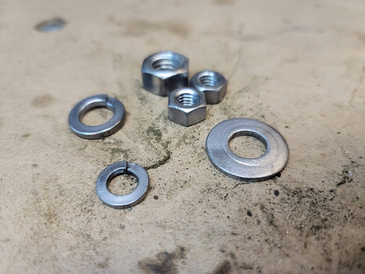
Next step was to clean up the wires and hardware, no point in buying new nuts and bolts if you can clean up the old ones! Also cleaned out the armature gaps.
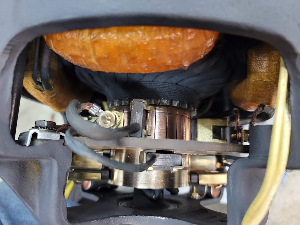
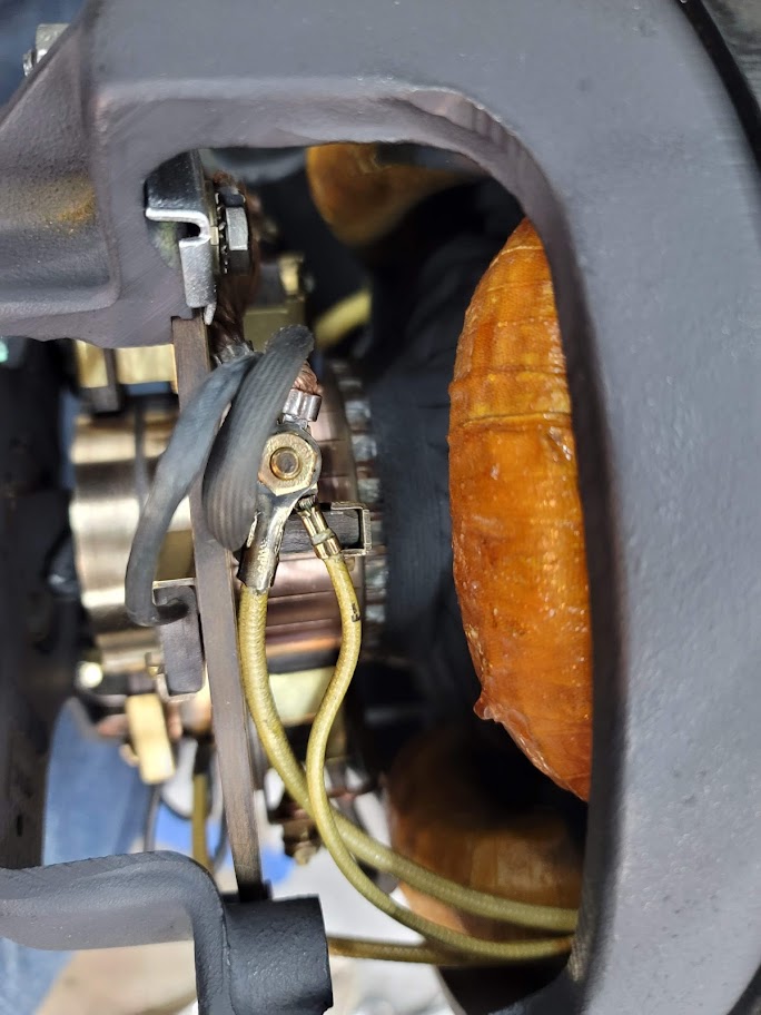
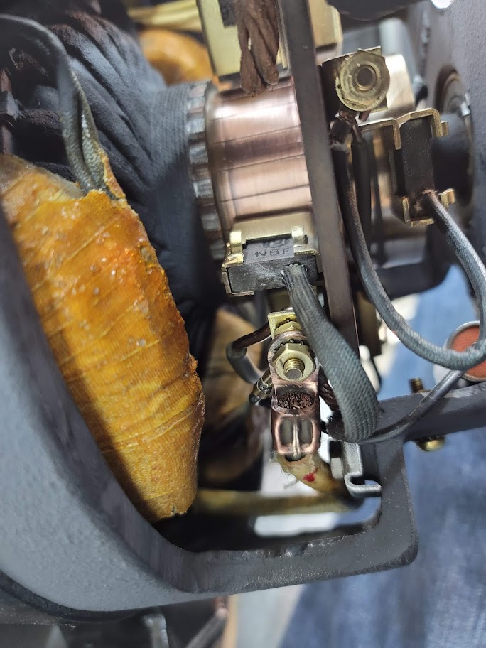
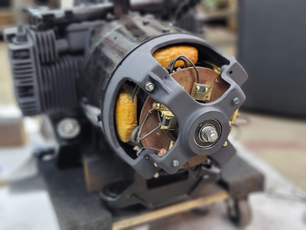
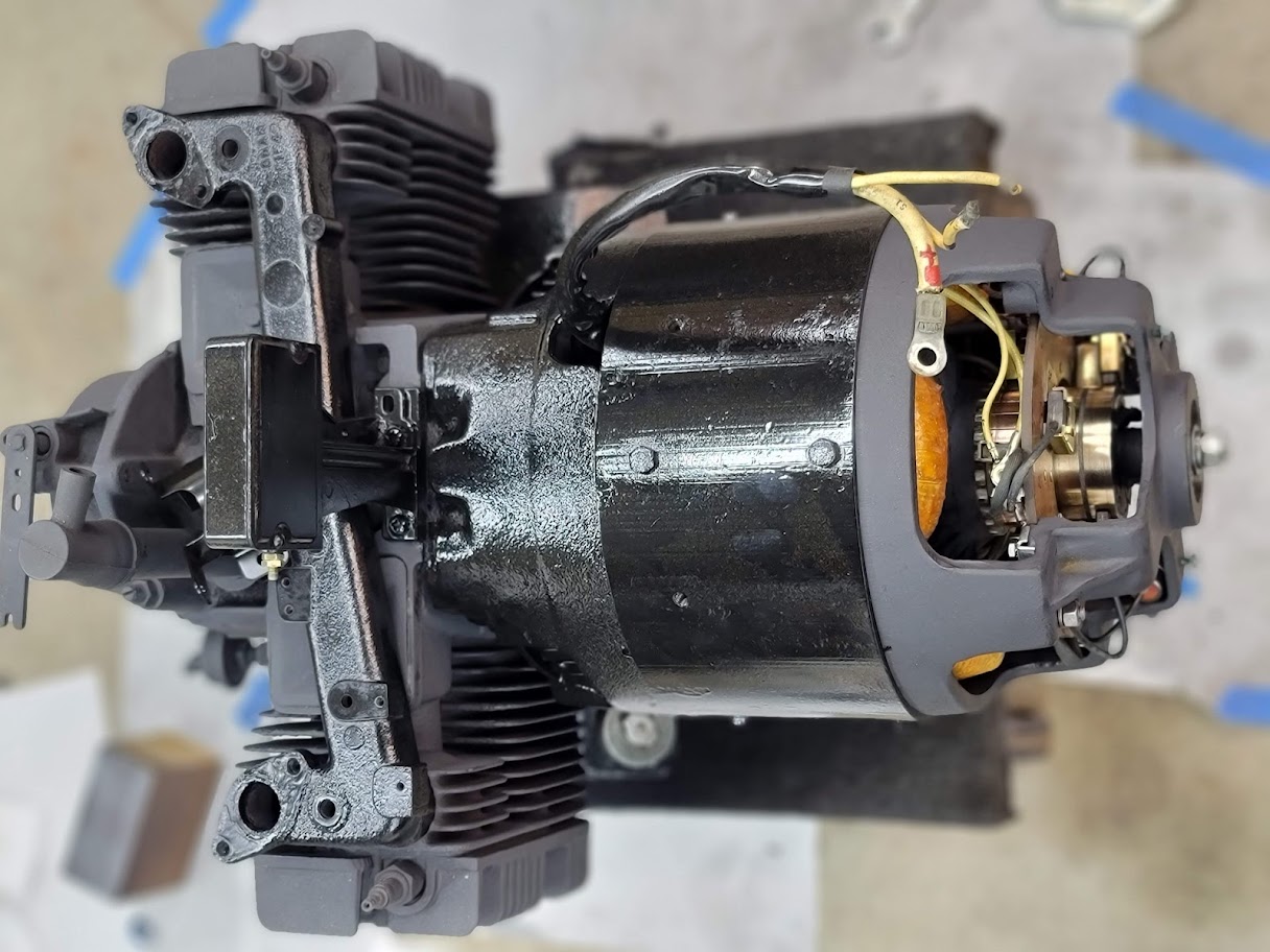
Got the back end bolted back on! Everything fit good, and after checking many reference photos I took as I progressed I believe I got every wire back where it needs to be and the brush assembly ‘clocked’ correctly.
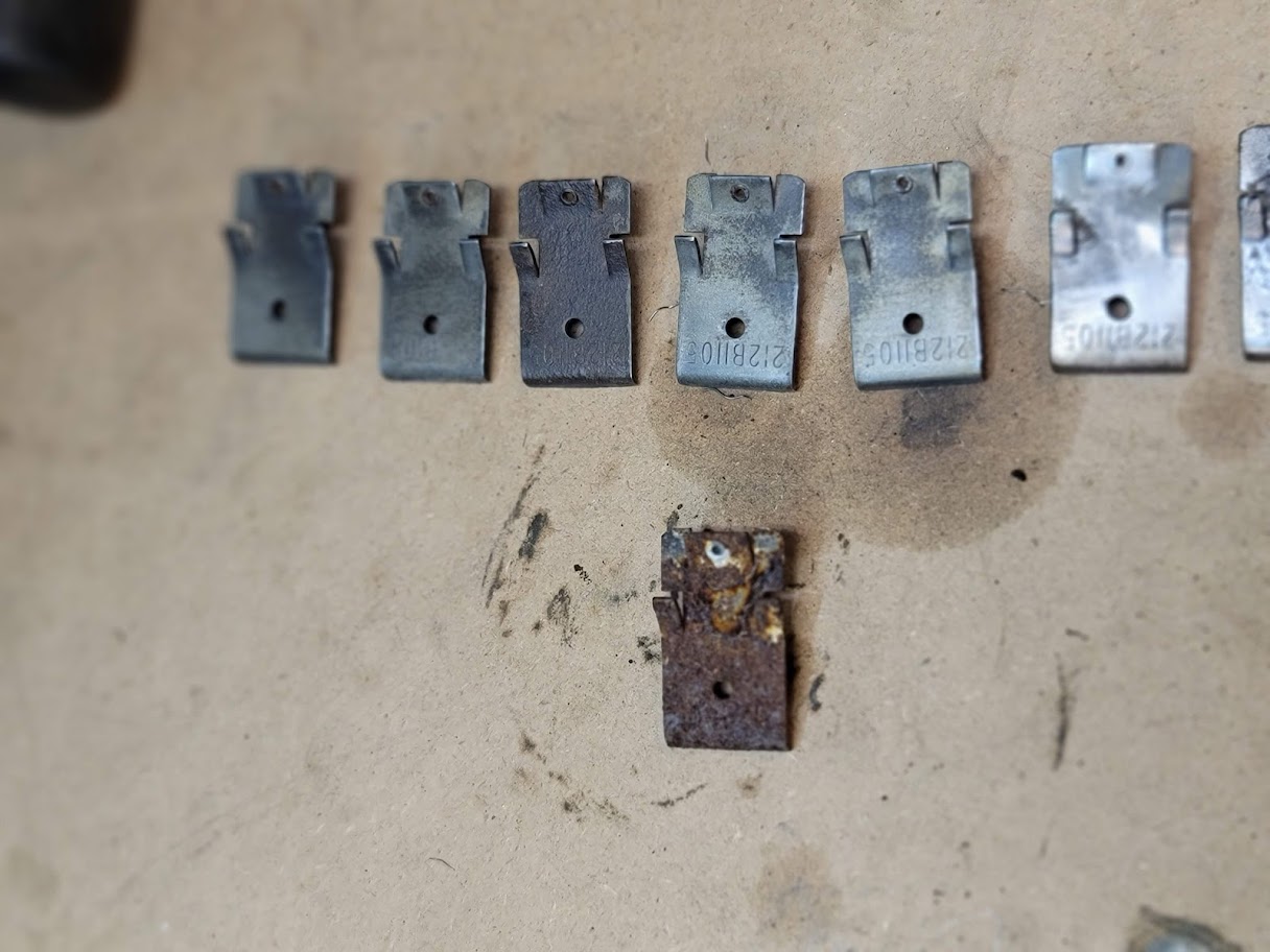
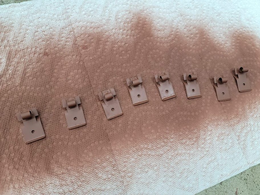
The Brush springs where a rusty mess, I left one untouched in the above photo to see how bad they where. But after lots of hand work they cleaned up nice! I have them in some ultra rust protecting primer now. Silver paint is next!
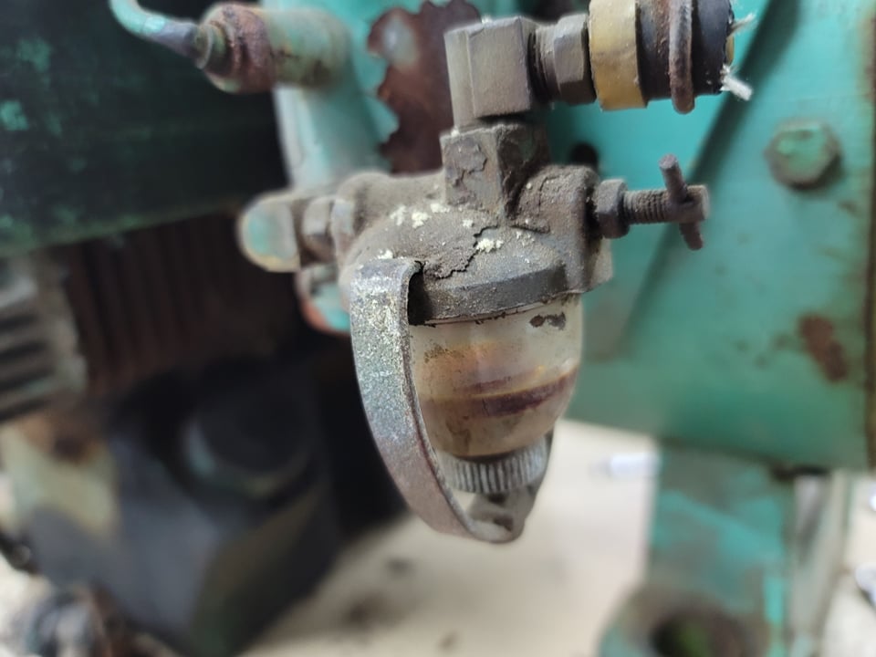
Remember this crusty mess of old varnished gas?
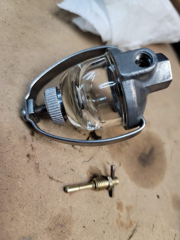
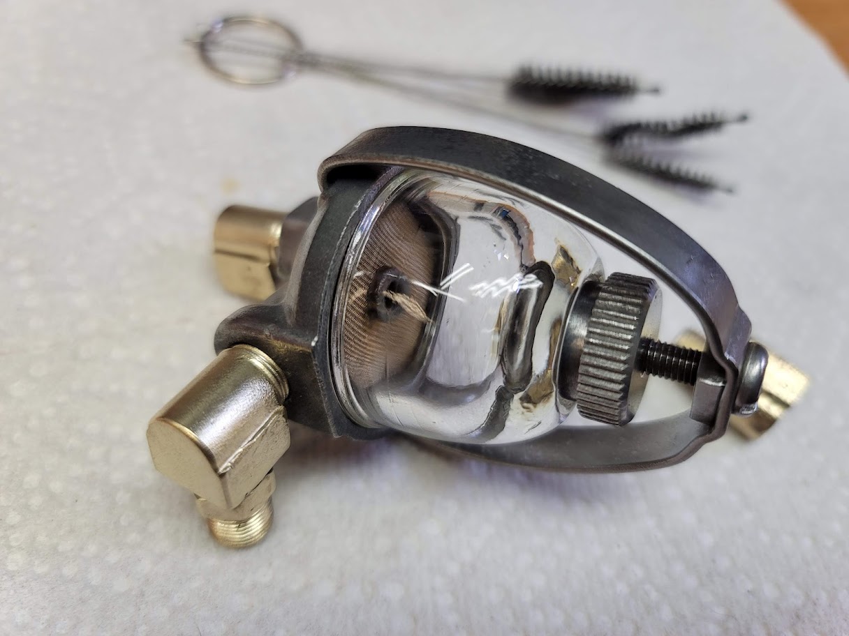

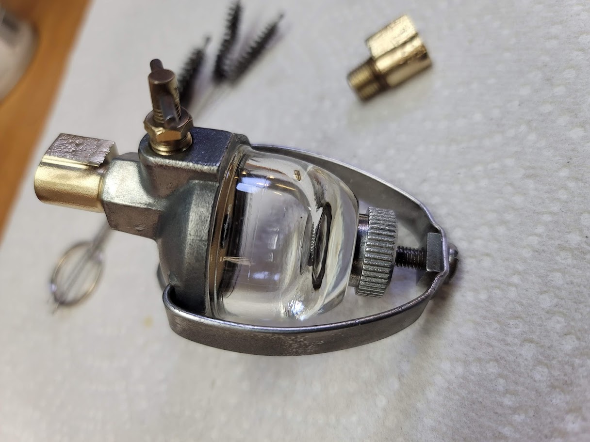
I would say it cleaned up real nice! Need to get it into paint next. ( Silver )
Got the intake painted, still need to grind the seal surfaces flat, but that is next after I finish painting the items above. More to come, stay tuned!
UPDATE: 1/29/2022 Lots of progress ( Got a working heater in the shop now so can work through th -4F weather we have been having here up north. )
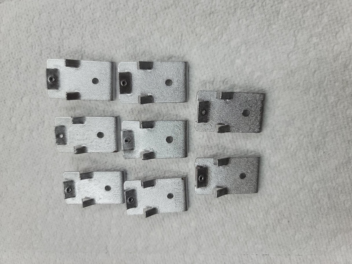
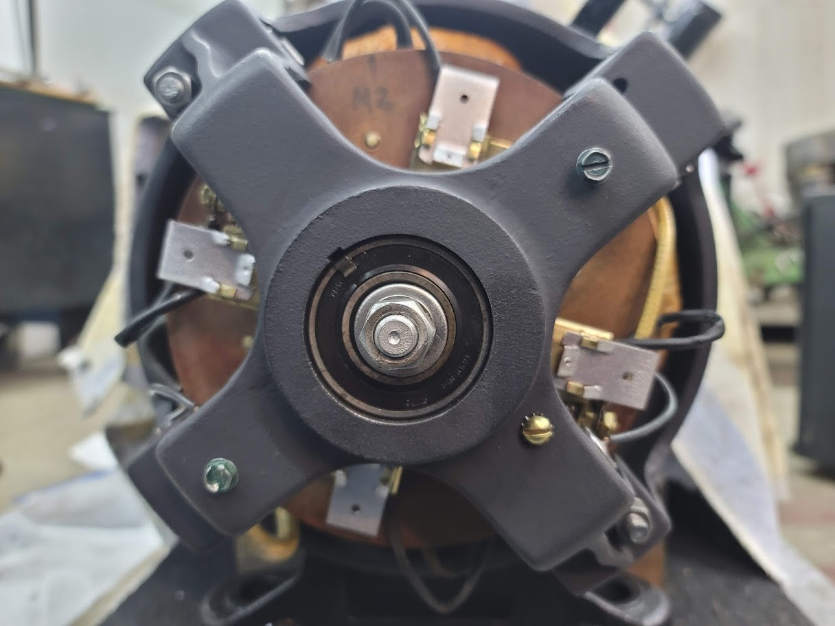
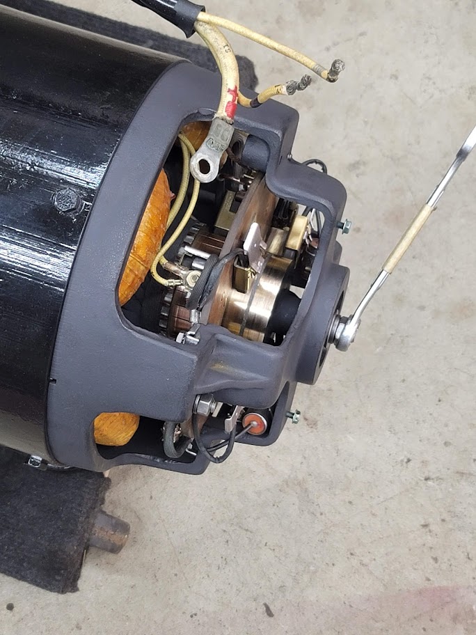
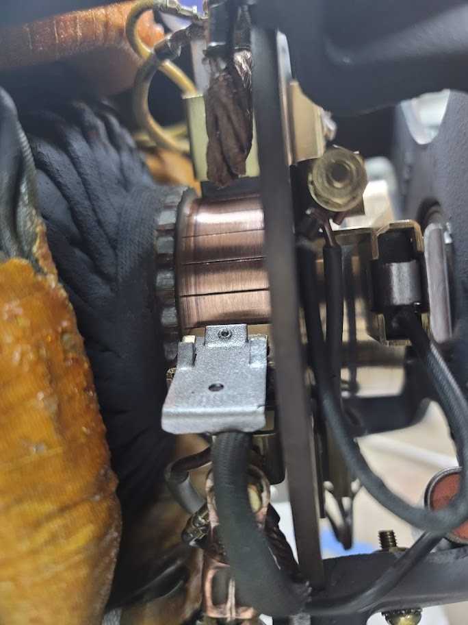
Brush springs painted and installed! Now for the back covers.
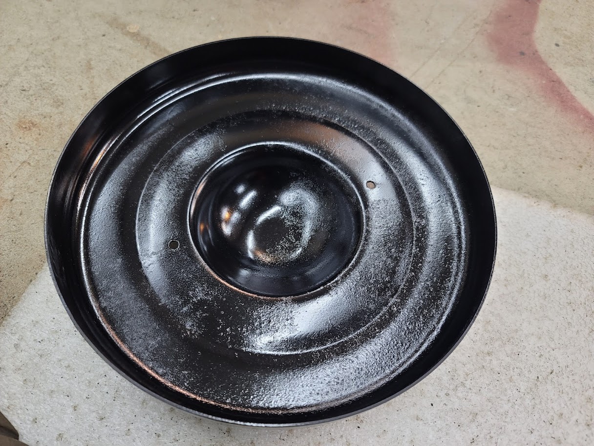
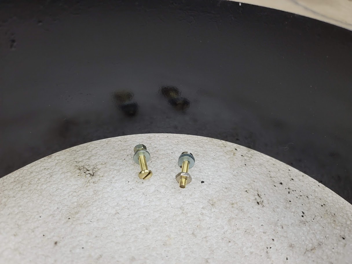
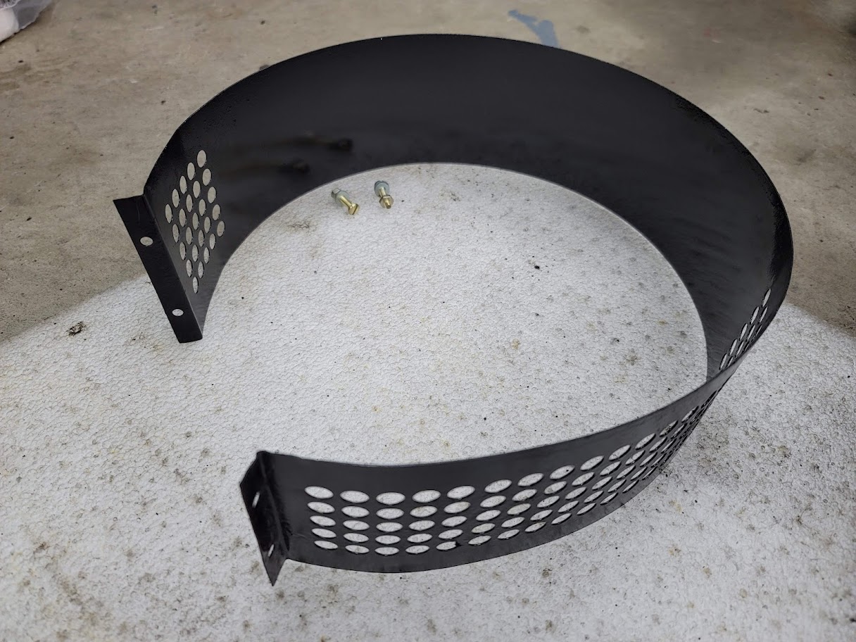
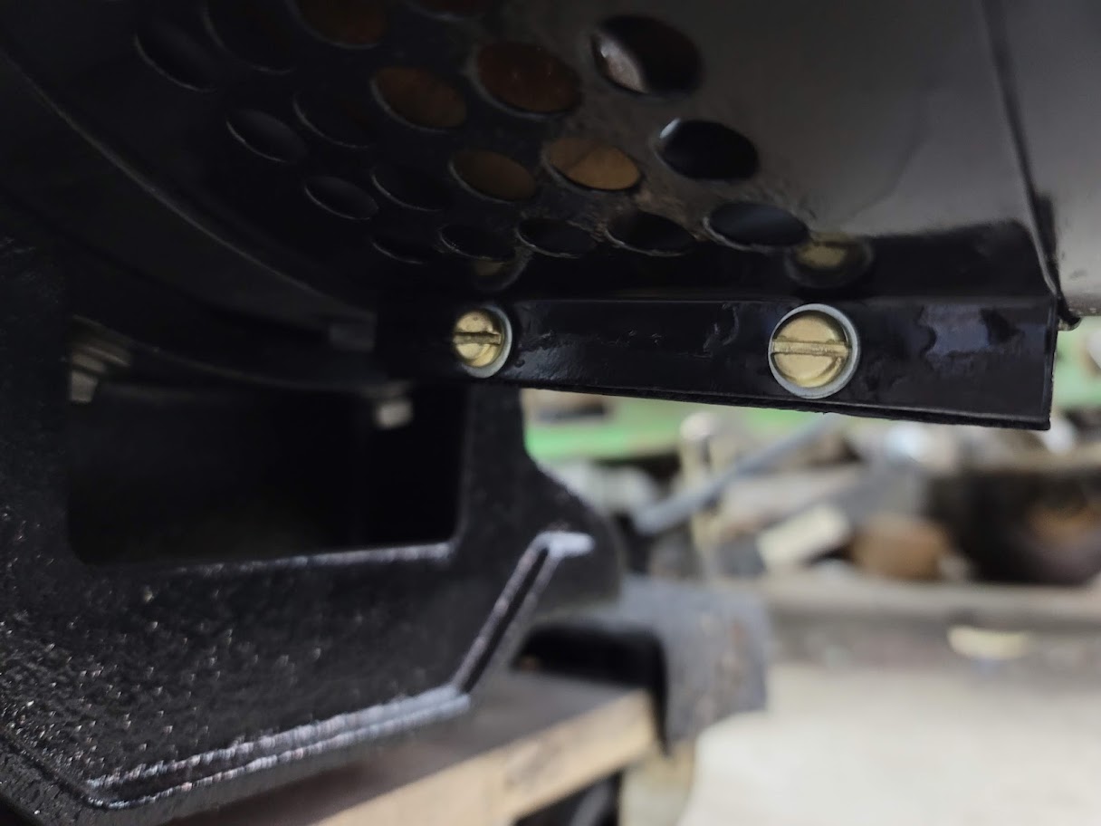
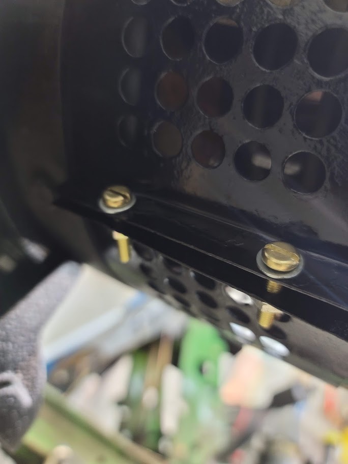
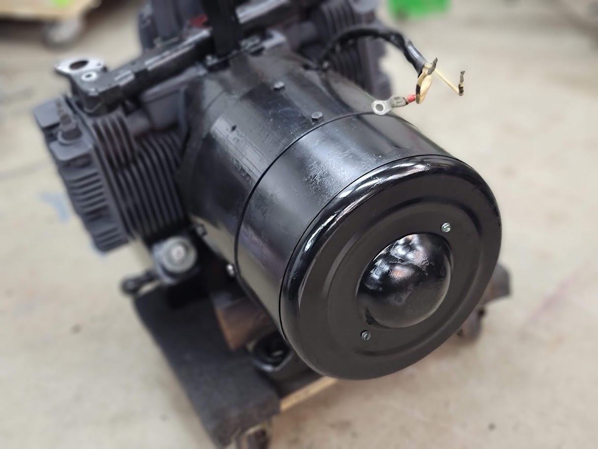
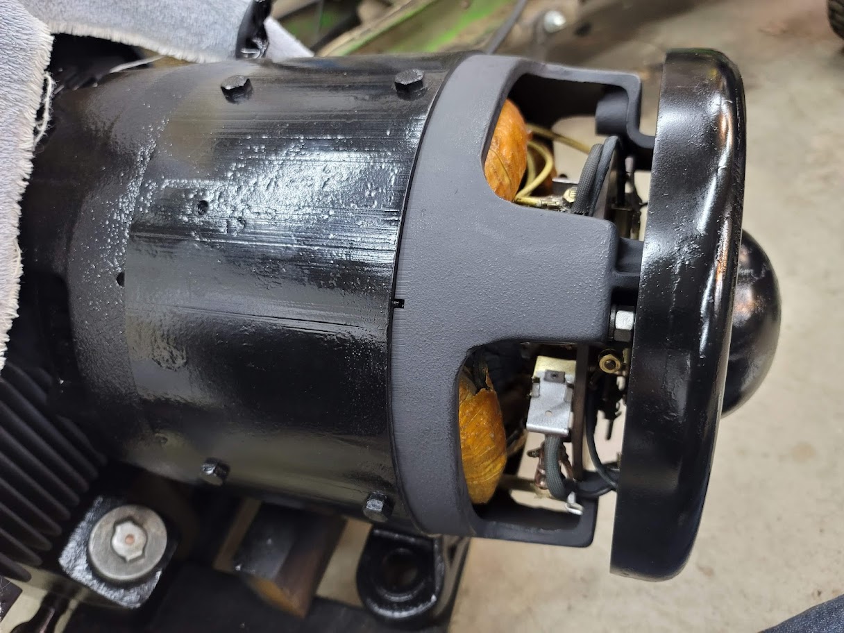
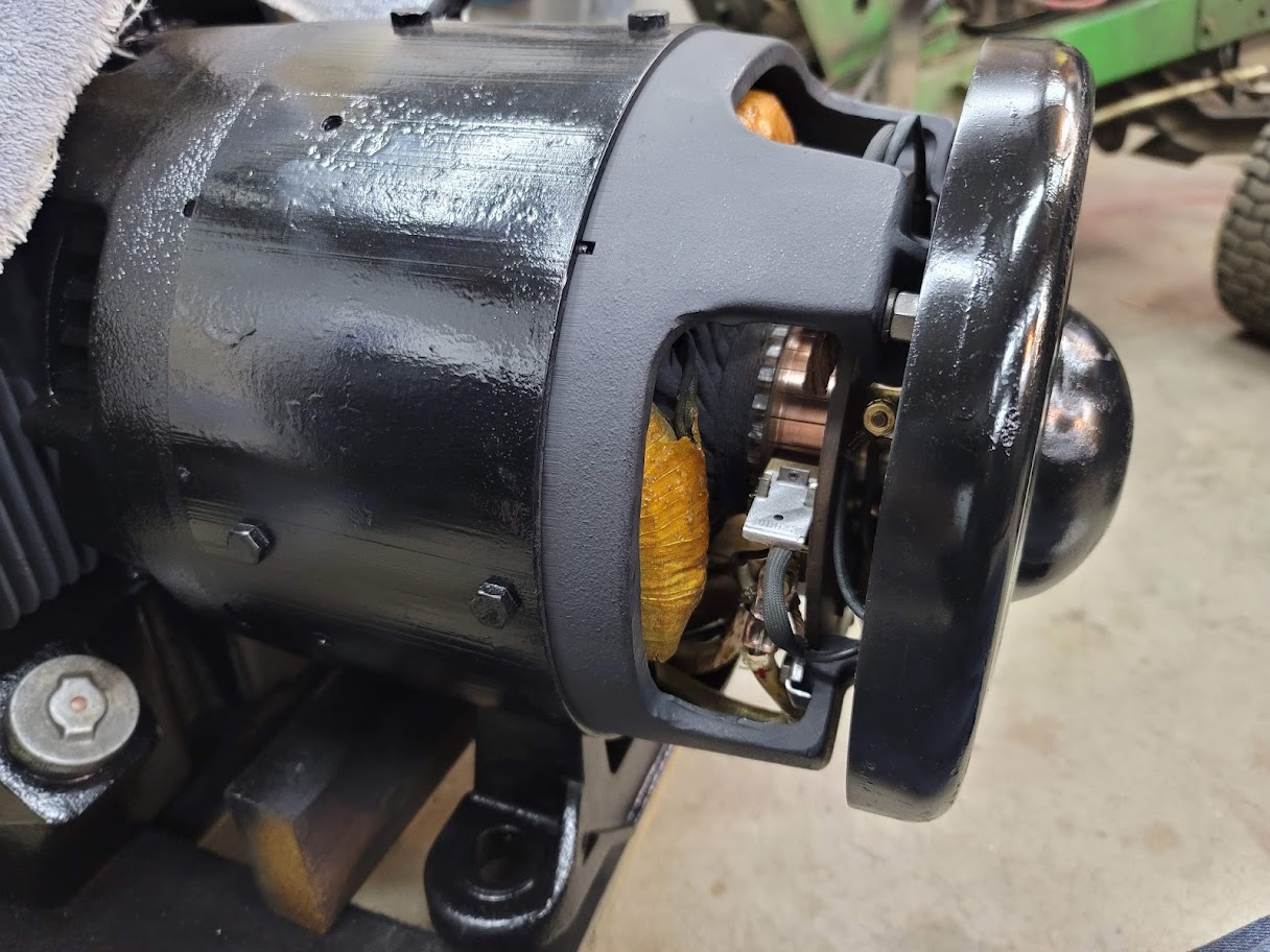
Feels a bit sad covering up all the shiny fancy bits, but it will keep them protected!
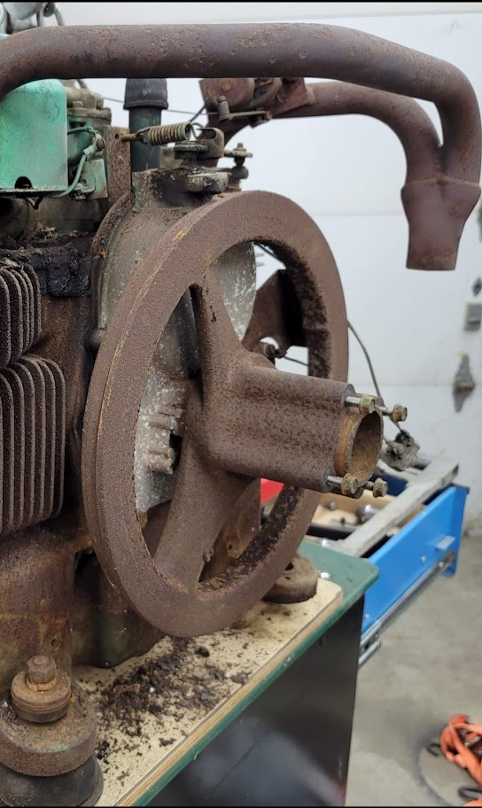
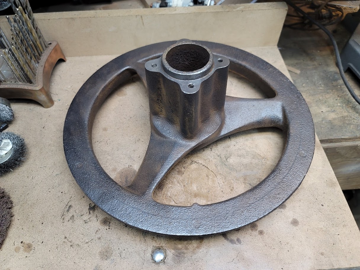
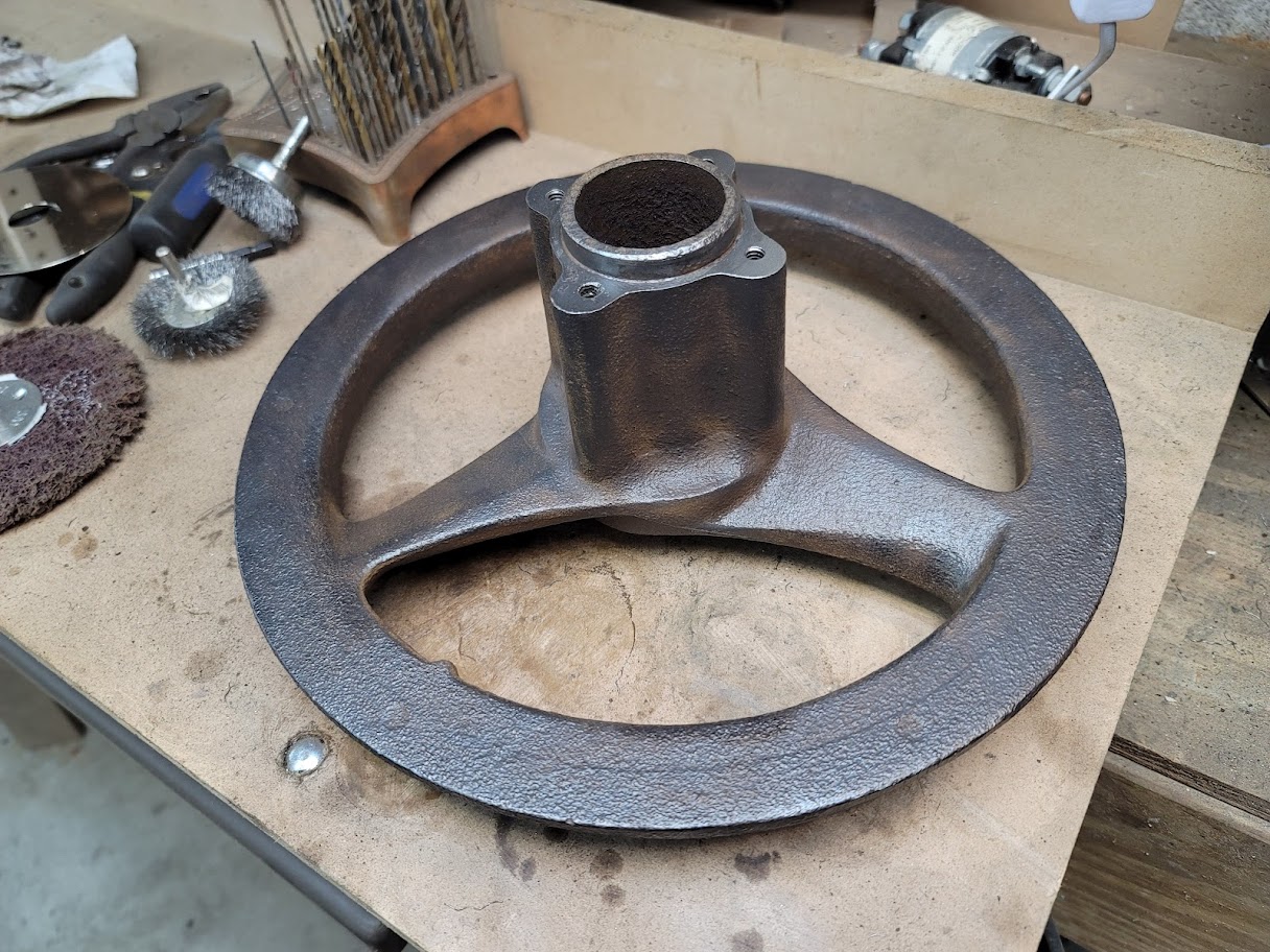
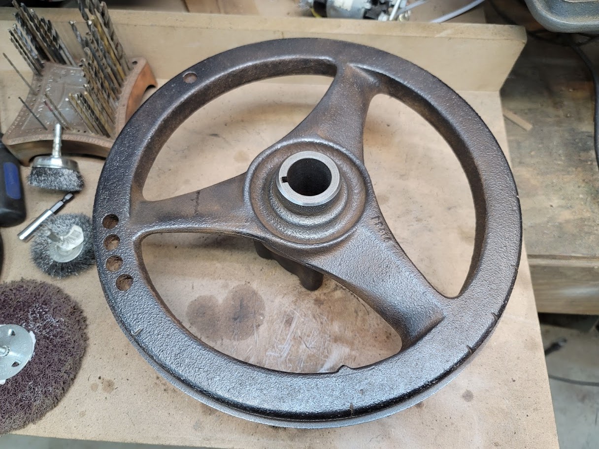
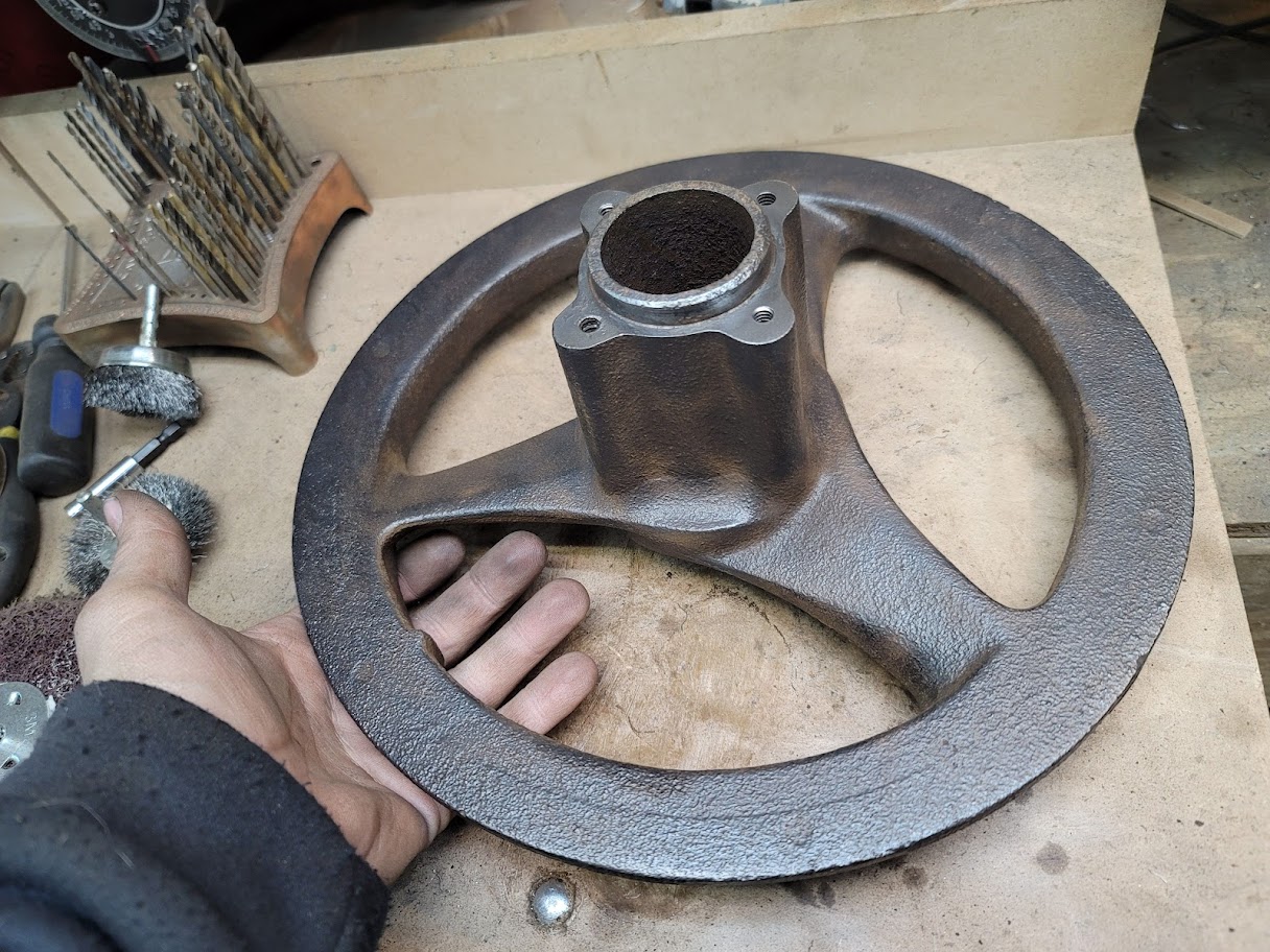
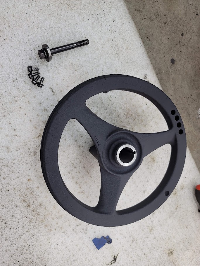
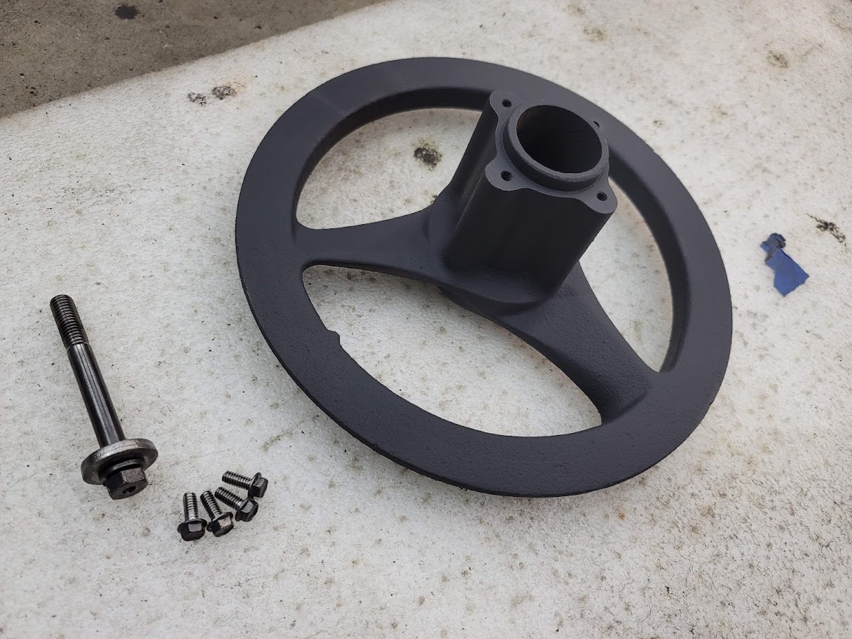
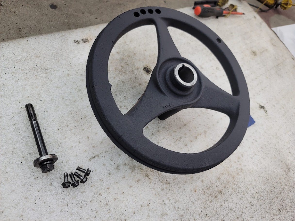
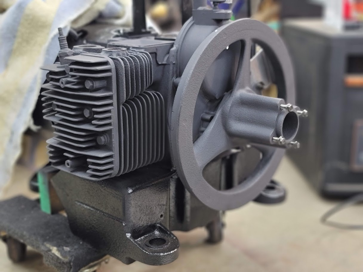
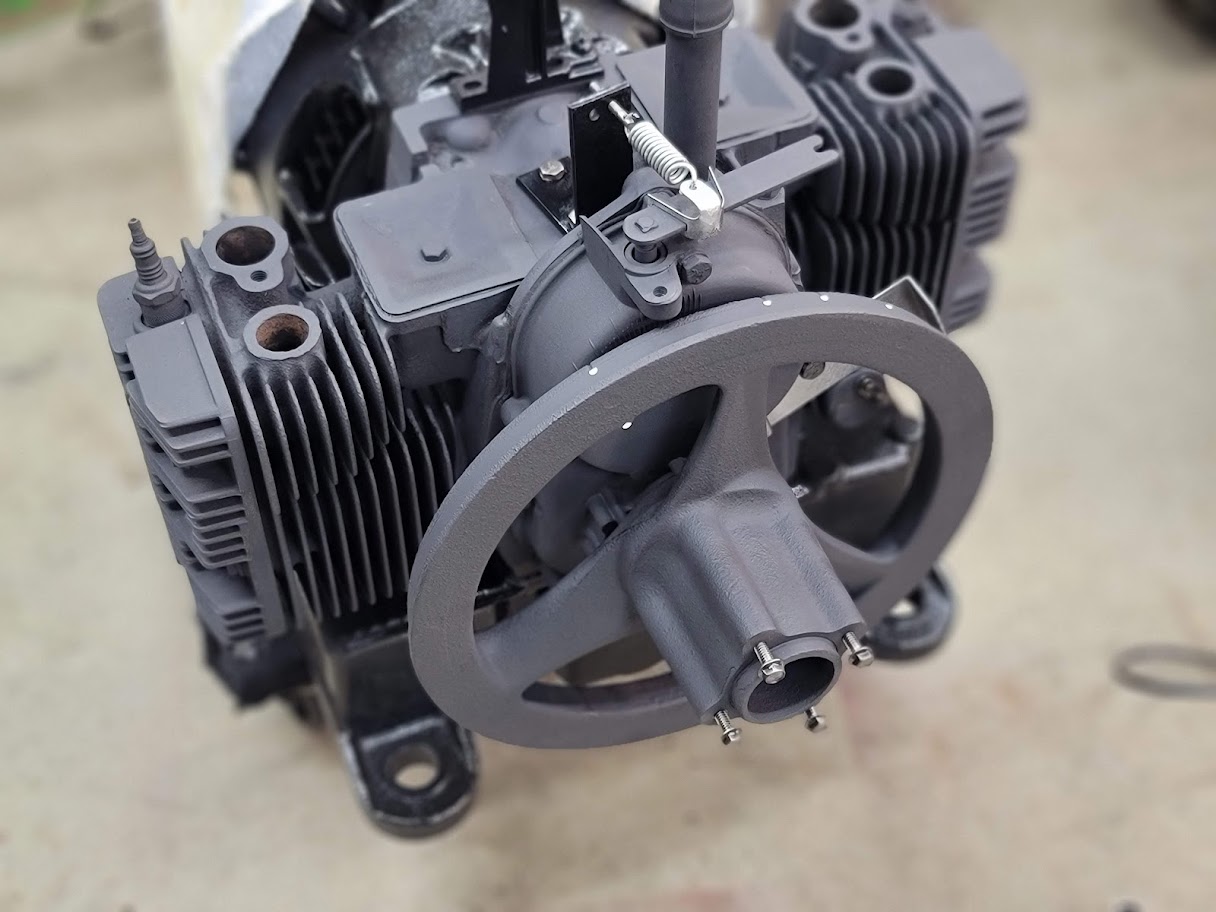
Remember the crusty flywheel? I sure do! many hours with just about every wire wheel shape I own to get the flywheel clean and in paint!
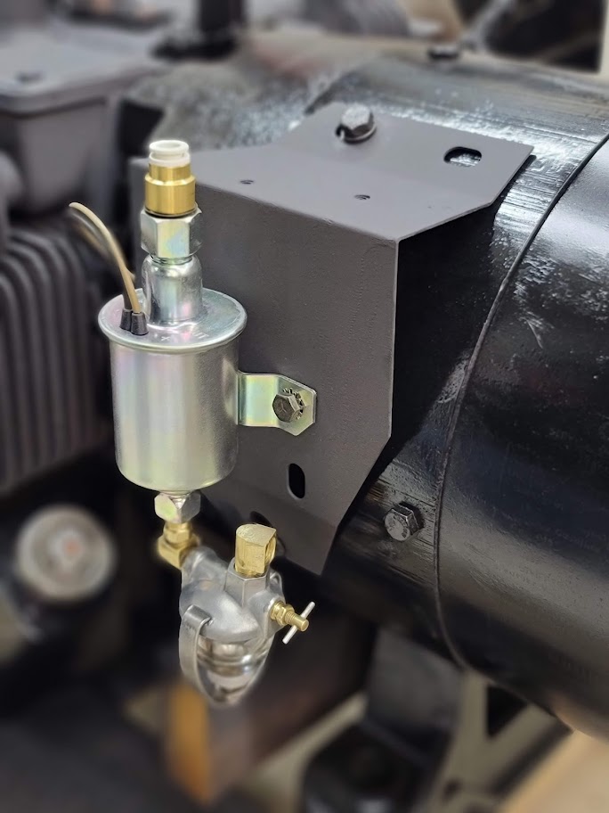
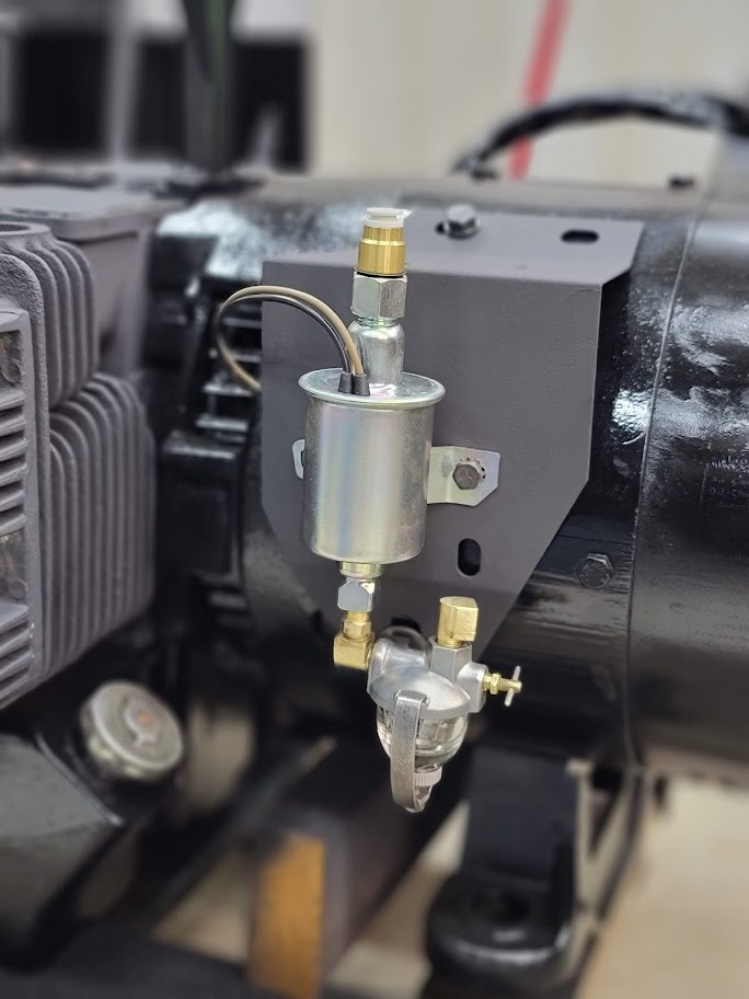
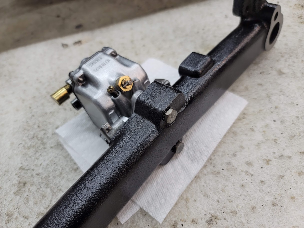
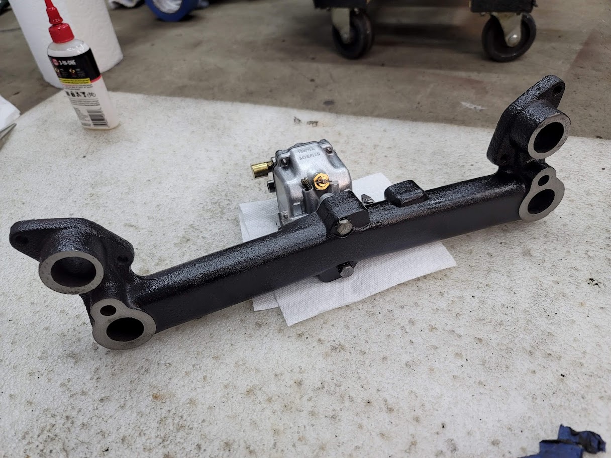
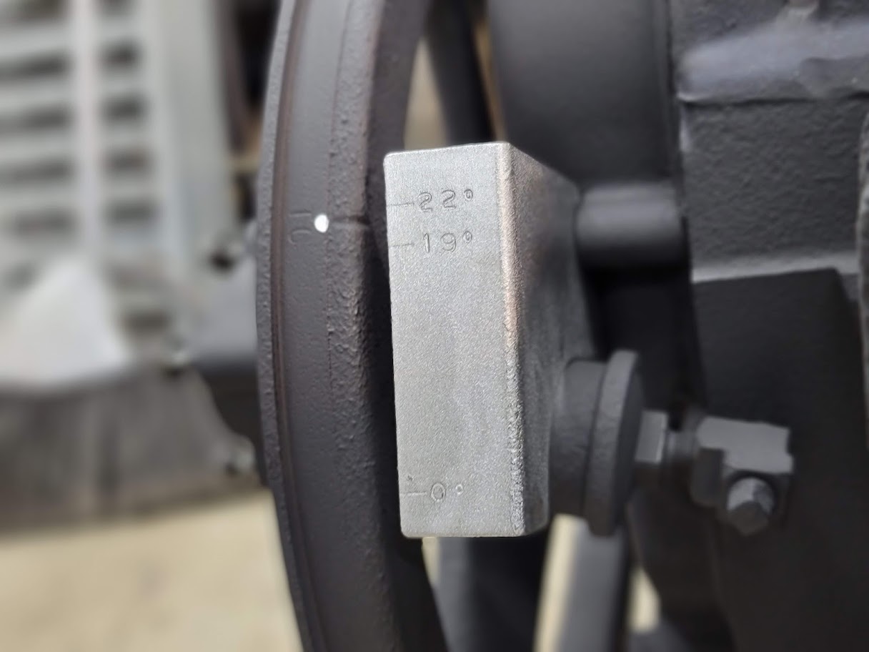
Got the new fuel pump, carb, and timing markers installed. Also took some time and surface ground the manifold for night tight sealing surfaces.
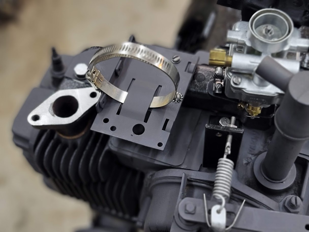
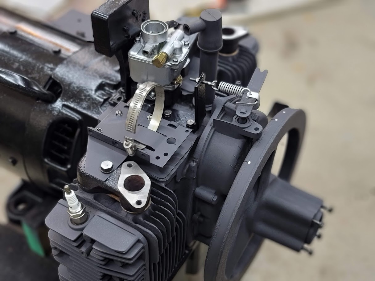
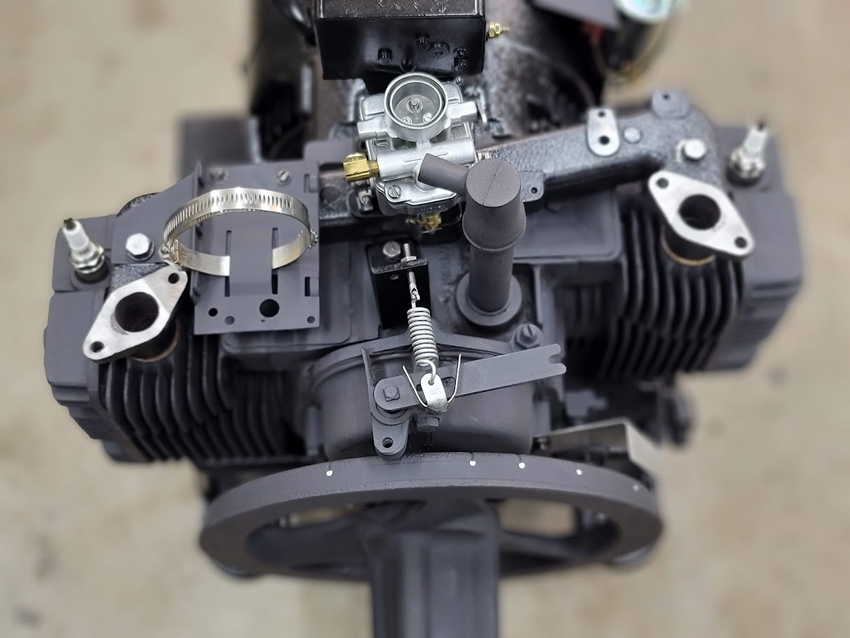
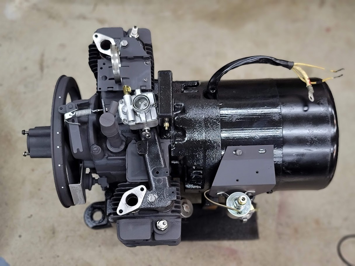
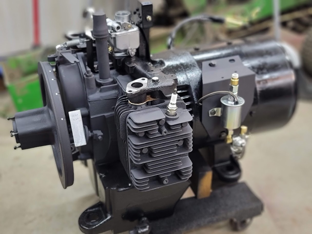
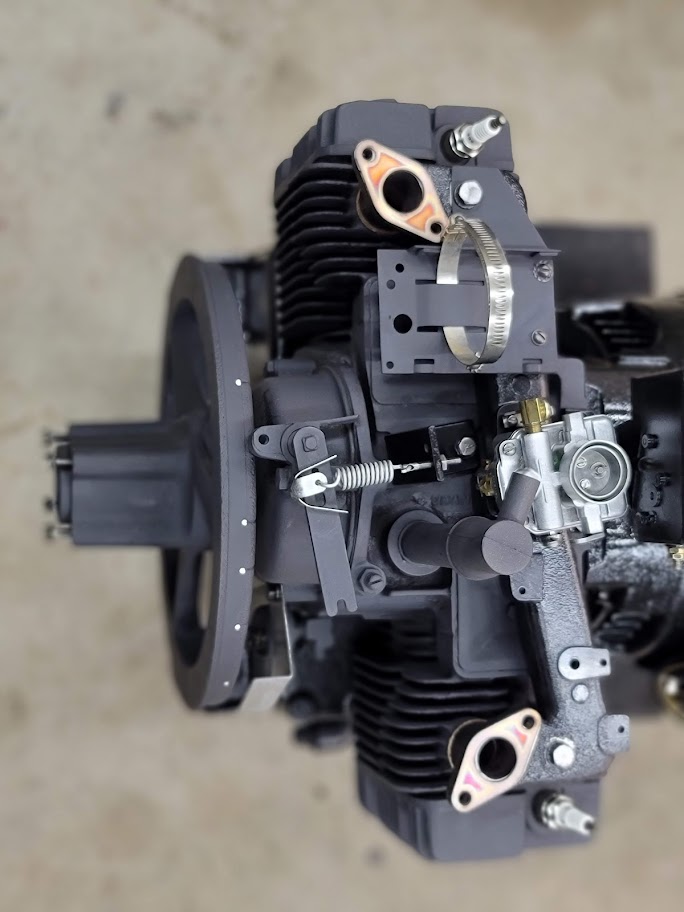
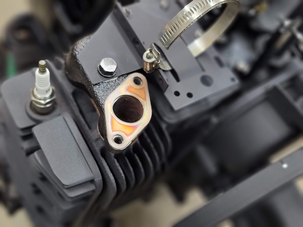
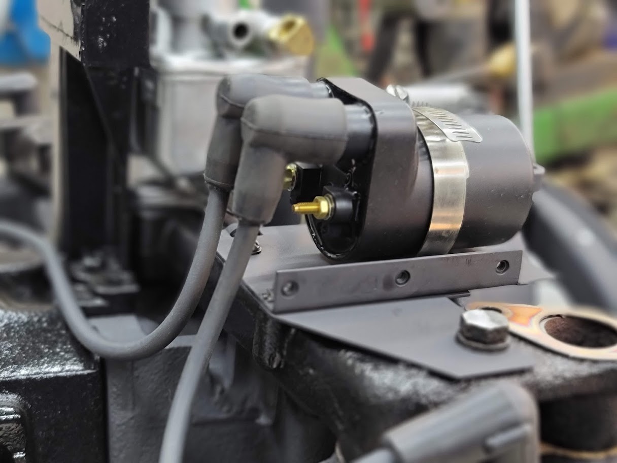
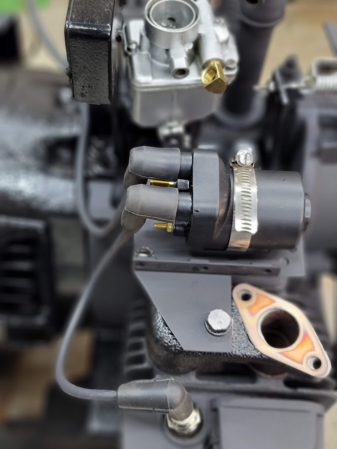
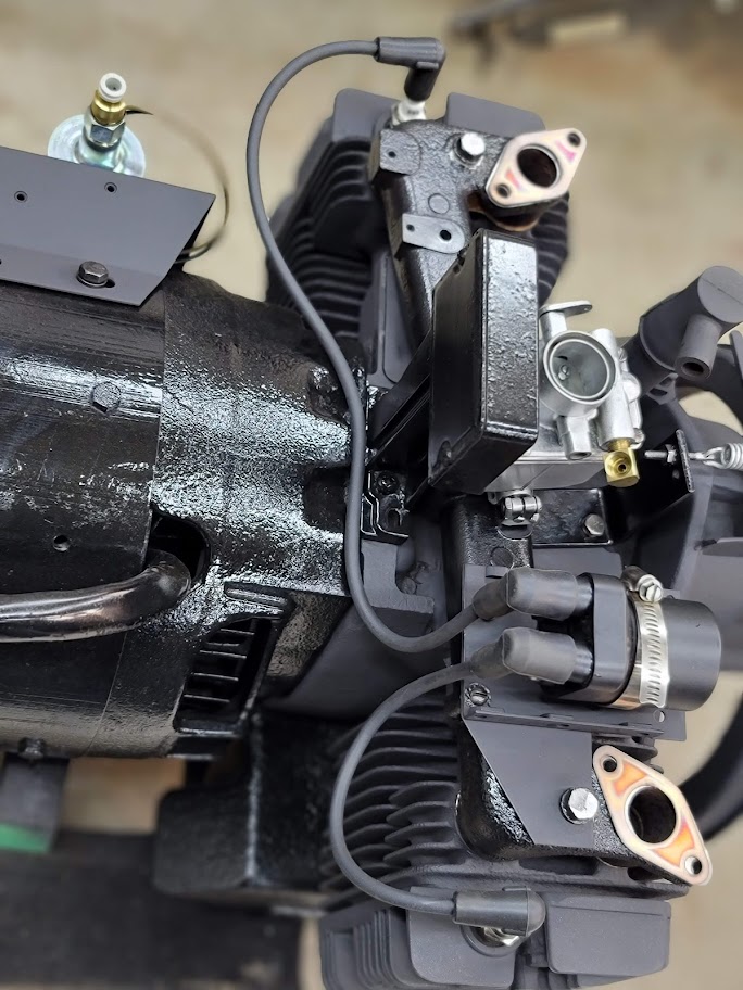
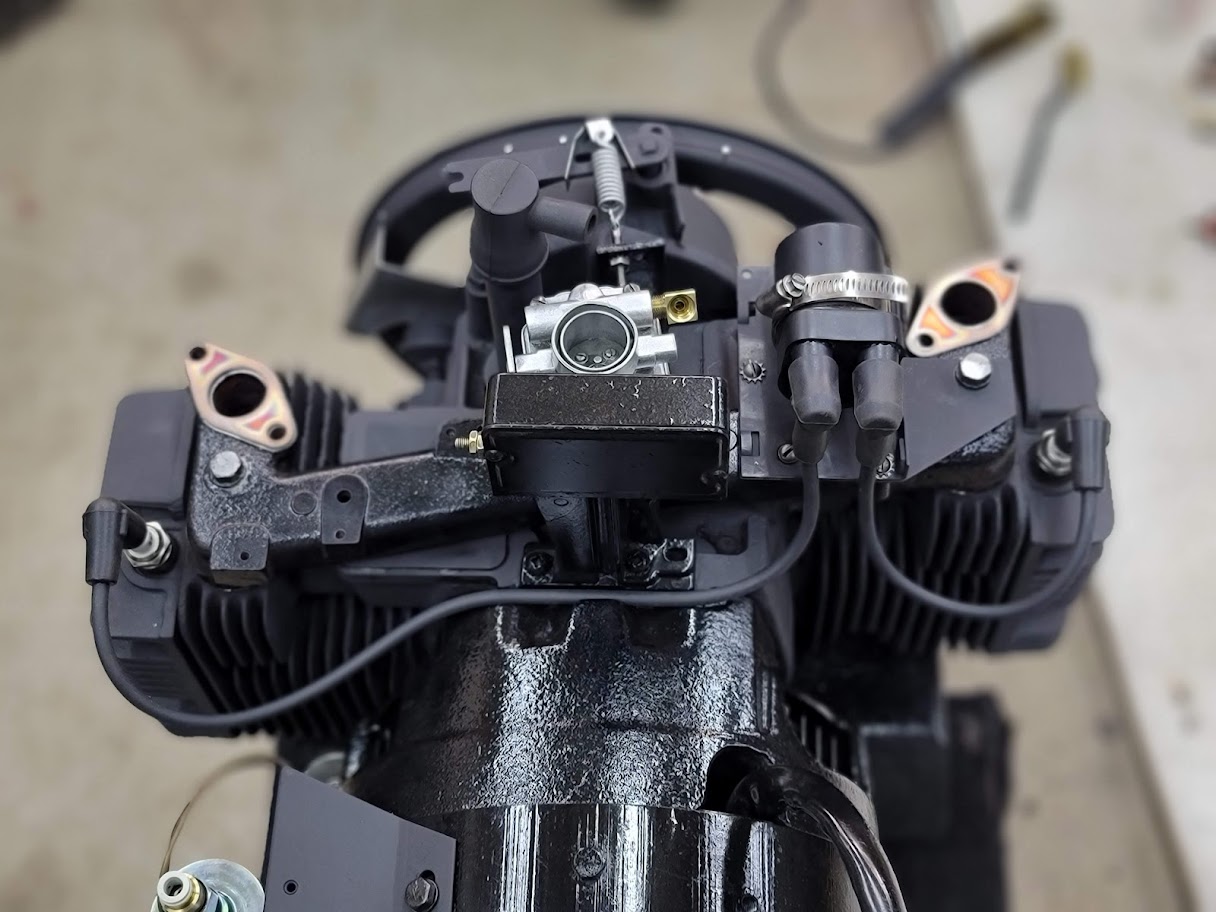
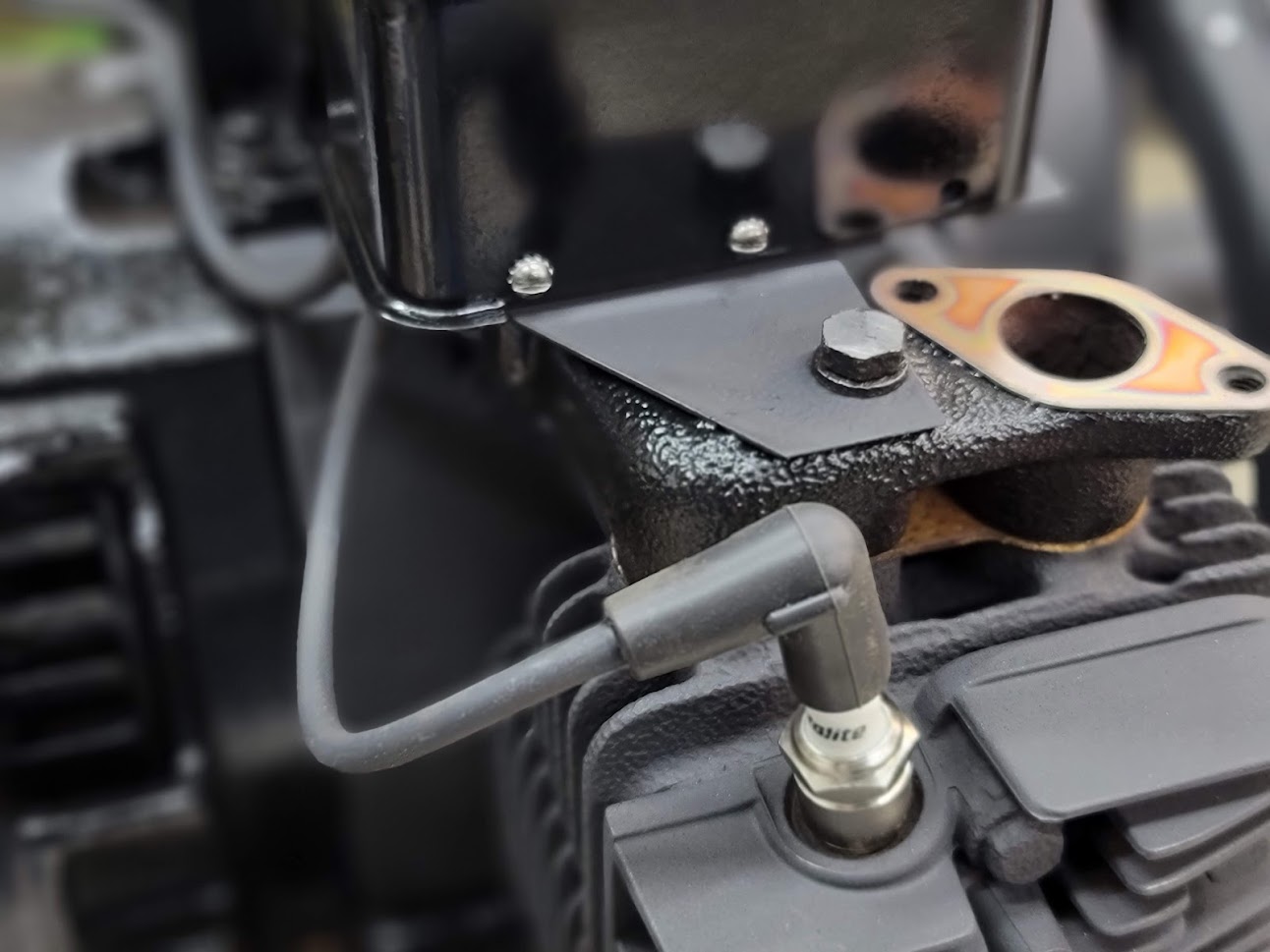
If you ever need to upgrade a CCK, I found a third party coil pack and wires work with the old mount and inside the old cover even!
Getting so close to first test fire! Need to install the exhaust, and do some wiring!
UPDATE: 1/30/2022 Got more parts installed, and very close to first test fire!
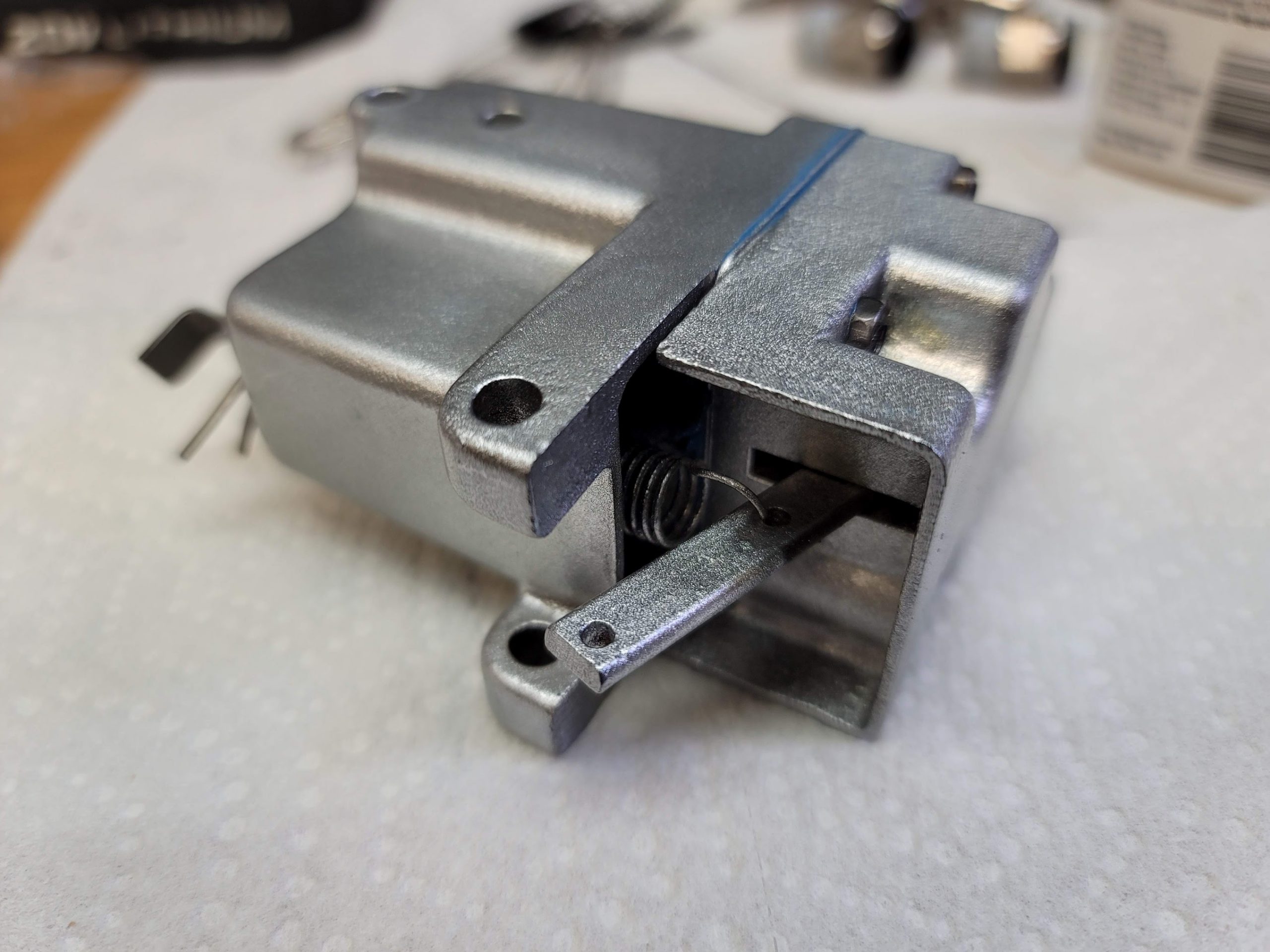
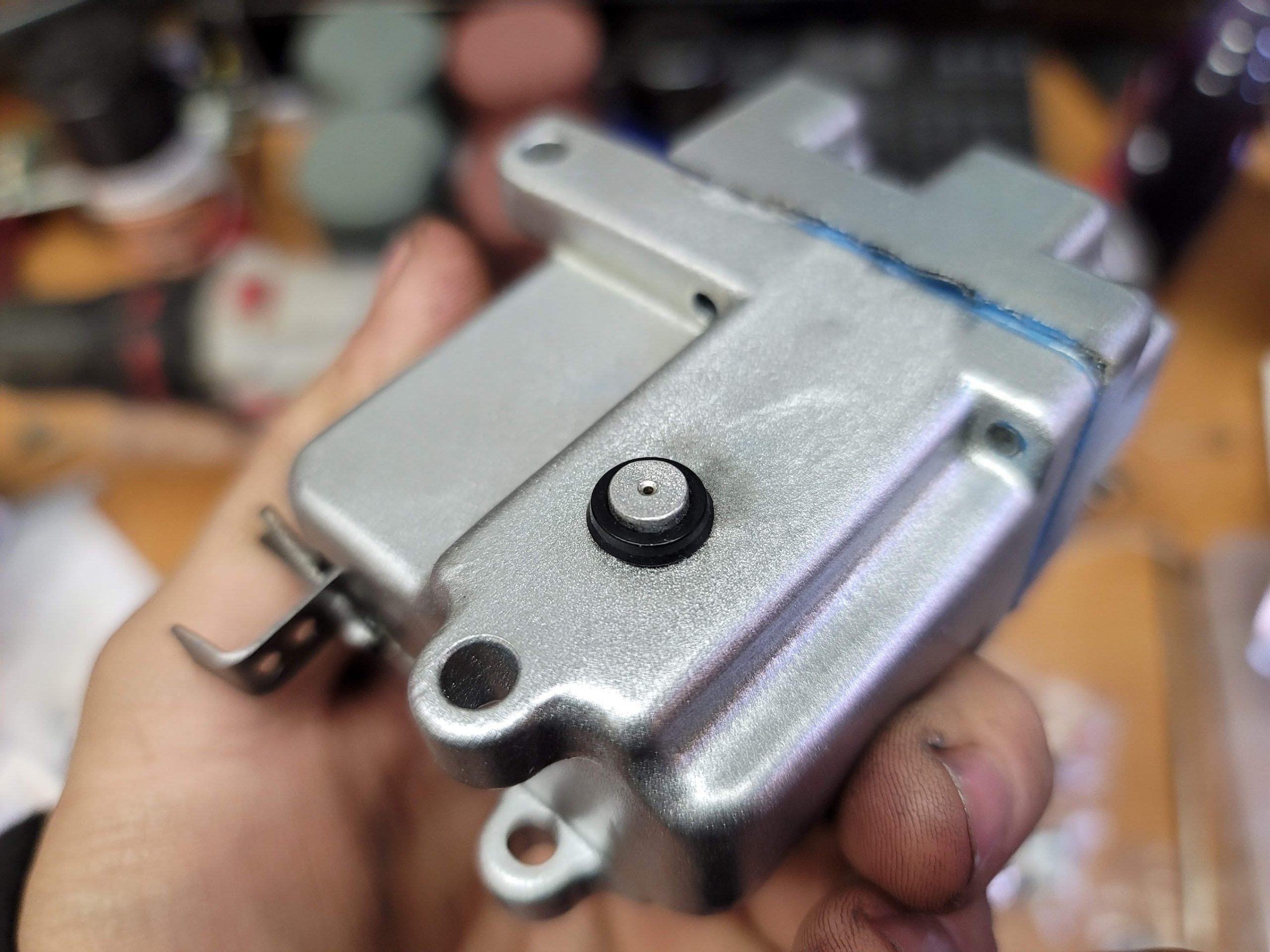
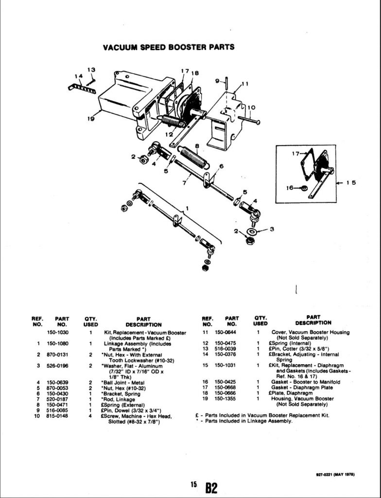
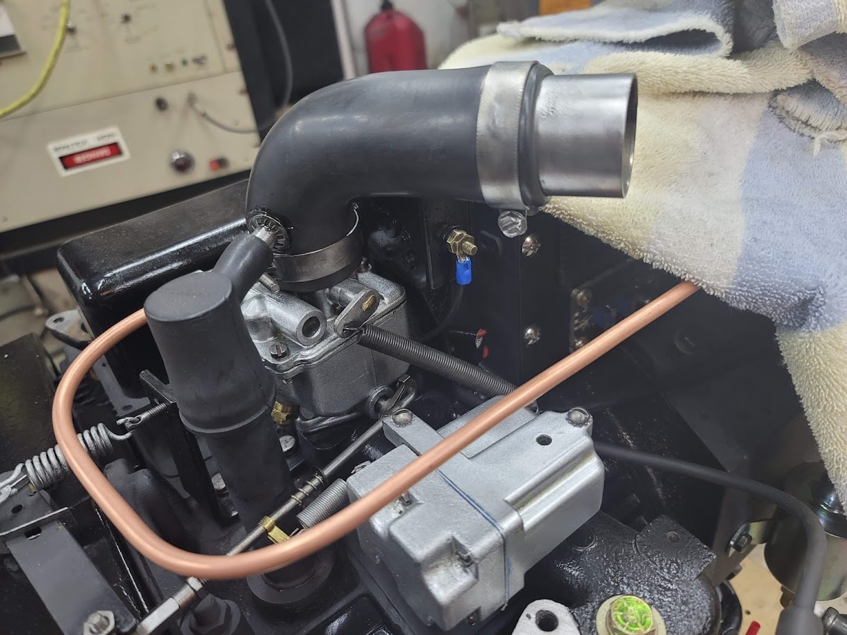
The vacuum booster has been rebuilt and got a coat of paint, I found rubber O ring to replace the old gasket. This seals on the intake, it will use manifold vacuum to pull on a plunger inside, this plunger will pull on the throttle to put extra force against the governor linkage, to give a boost on large power spikes. I could not find much info on it, so hope I did good rebuilding it.
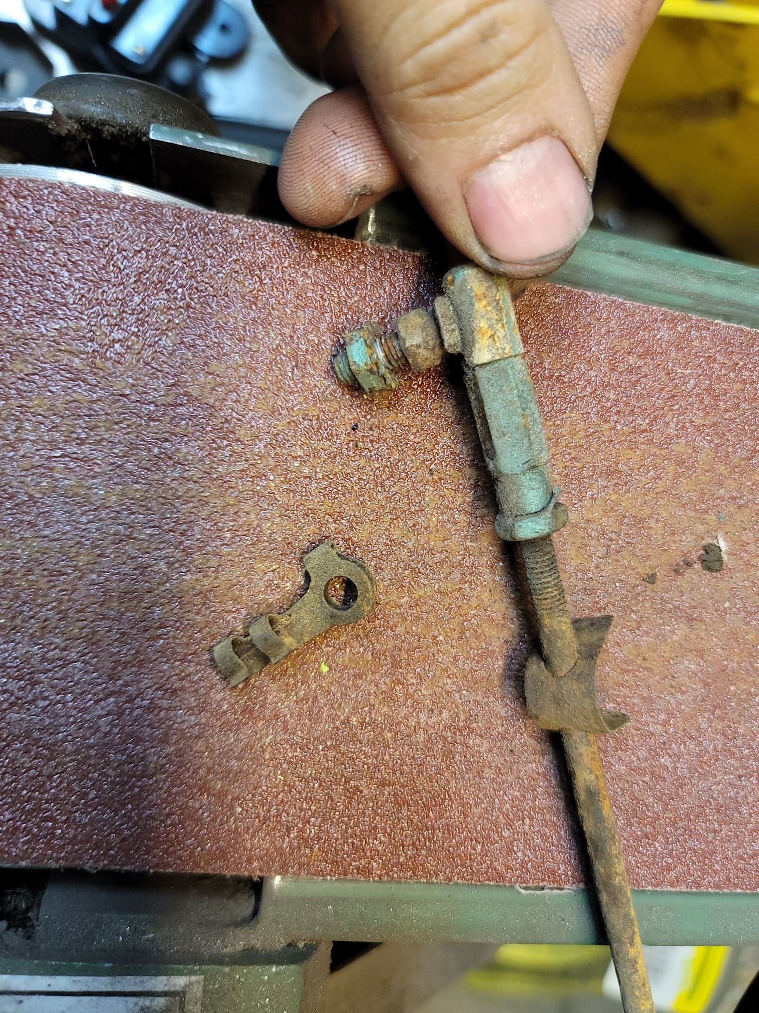
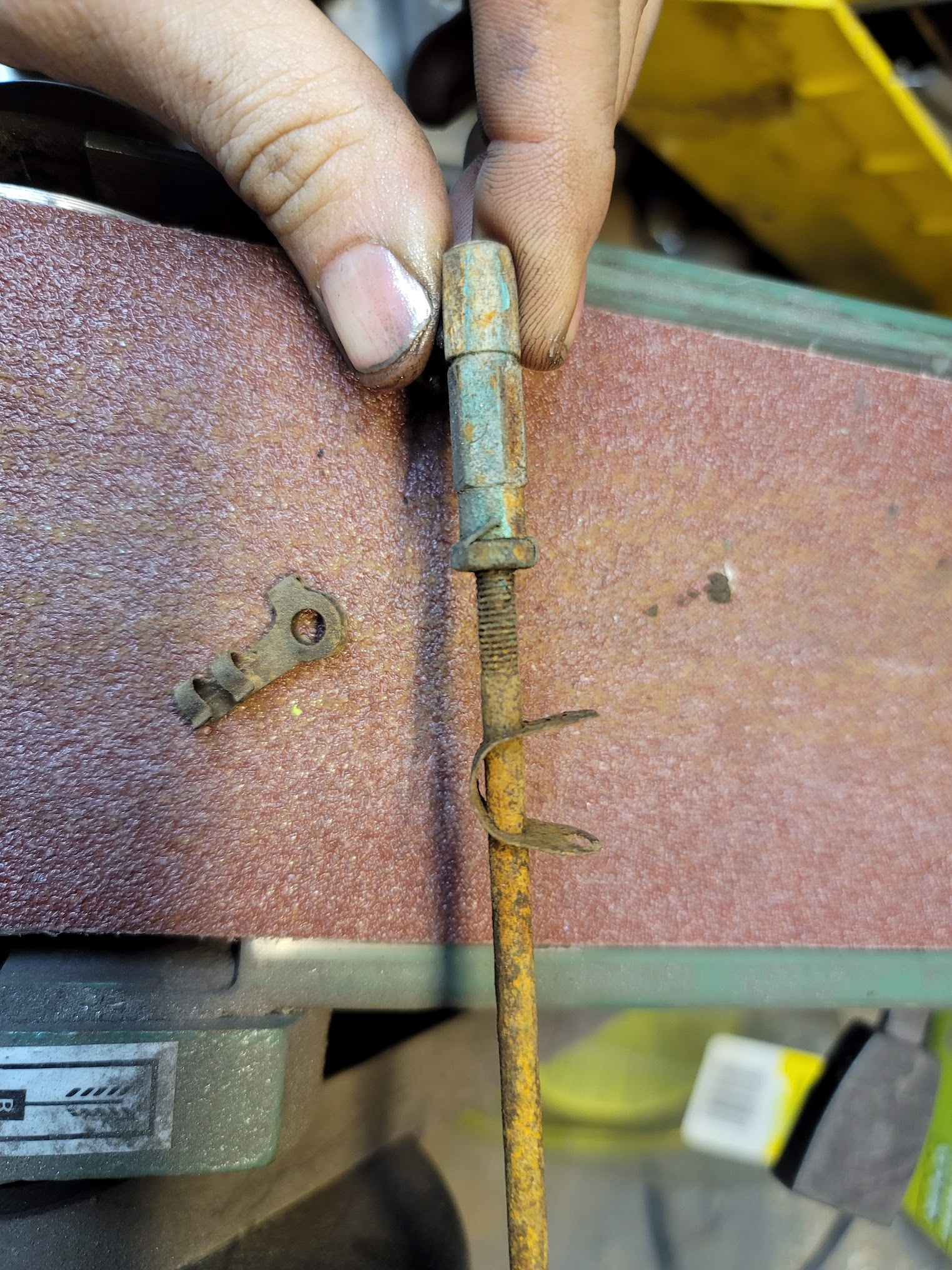
The old link setup was pretty rusty, the little spring tab was broken, and is $80! to replace it. These prices are crazy, so I built my own for now.. will find a proper line clamp soon. Also spend some time with the wire wheel, and she looks good as new!
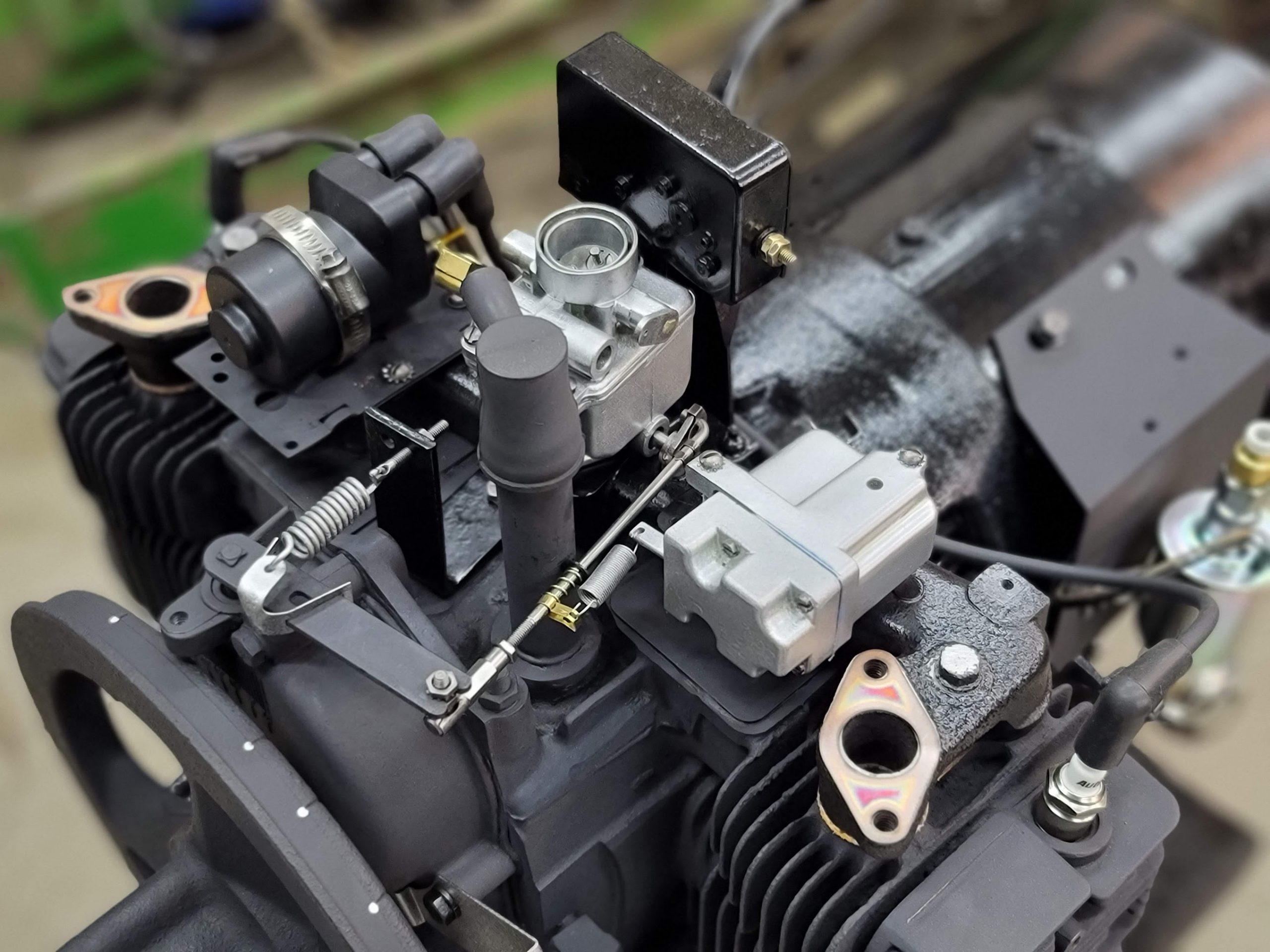
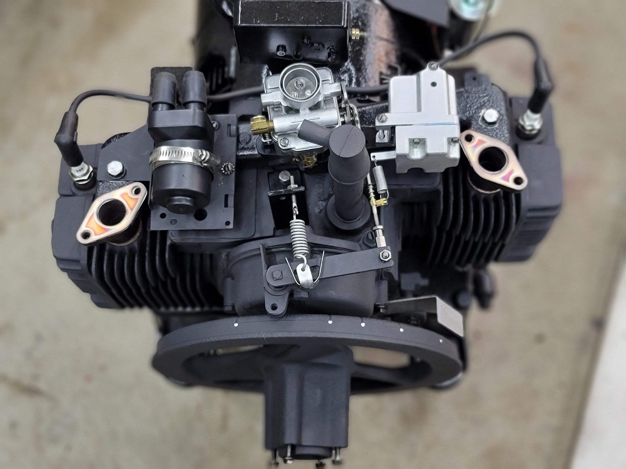
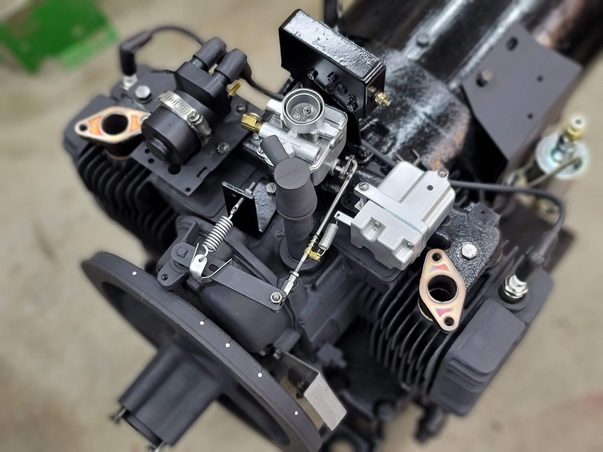
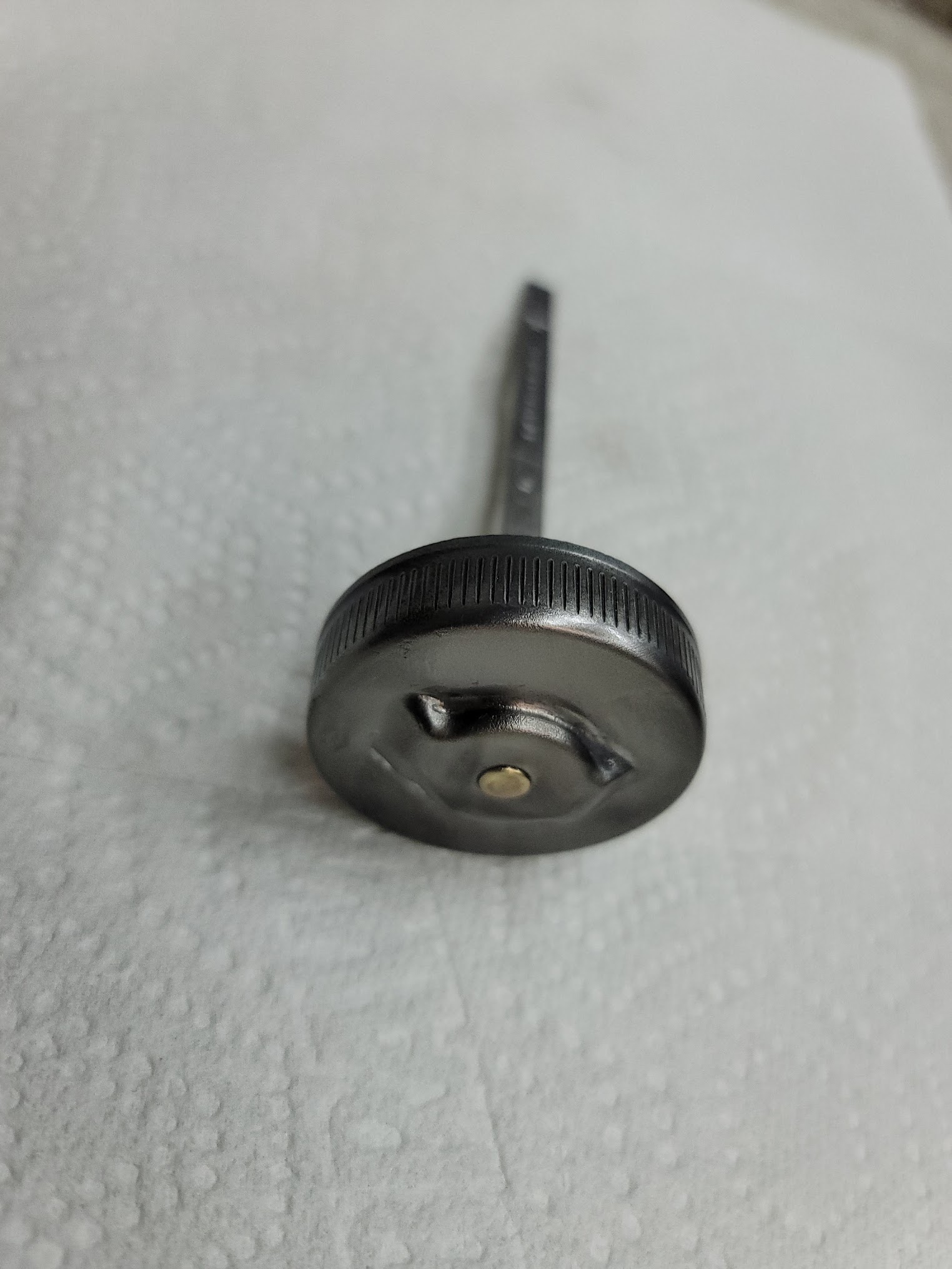
Next was a quick cleanup of the oil dipstick and cap.
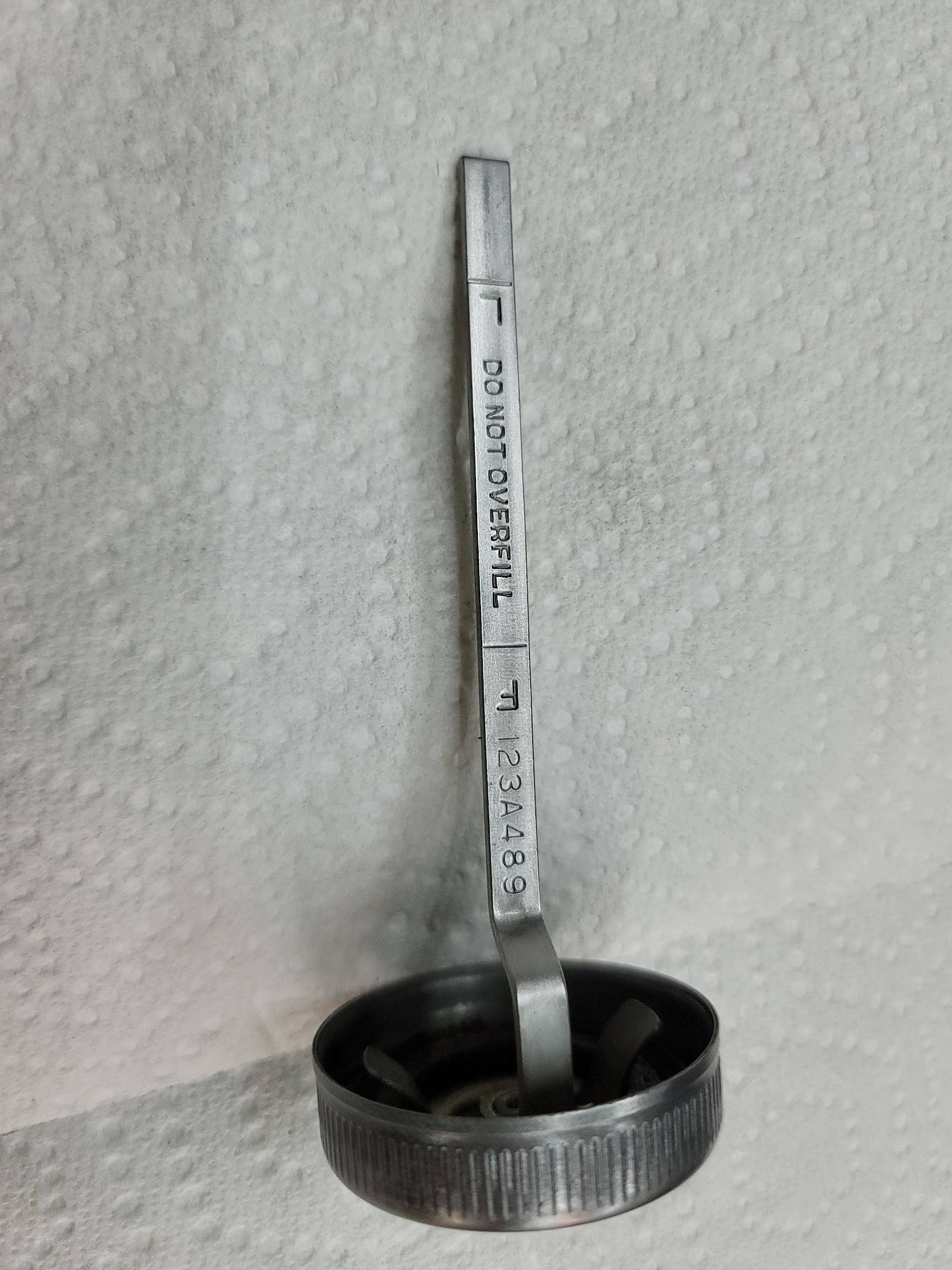
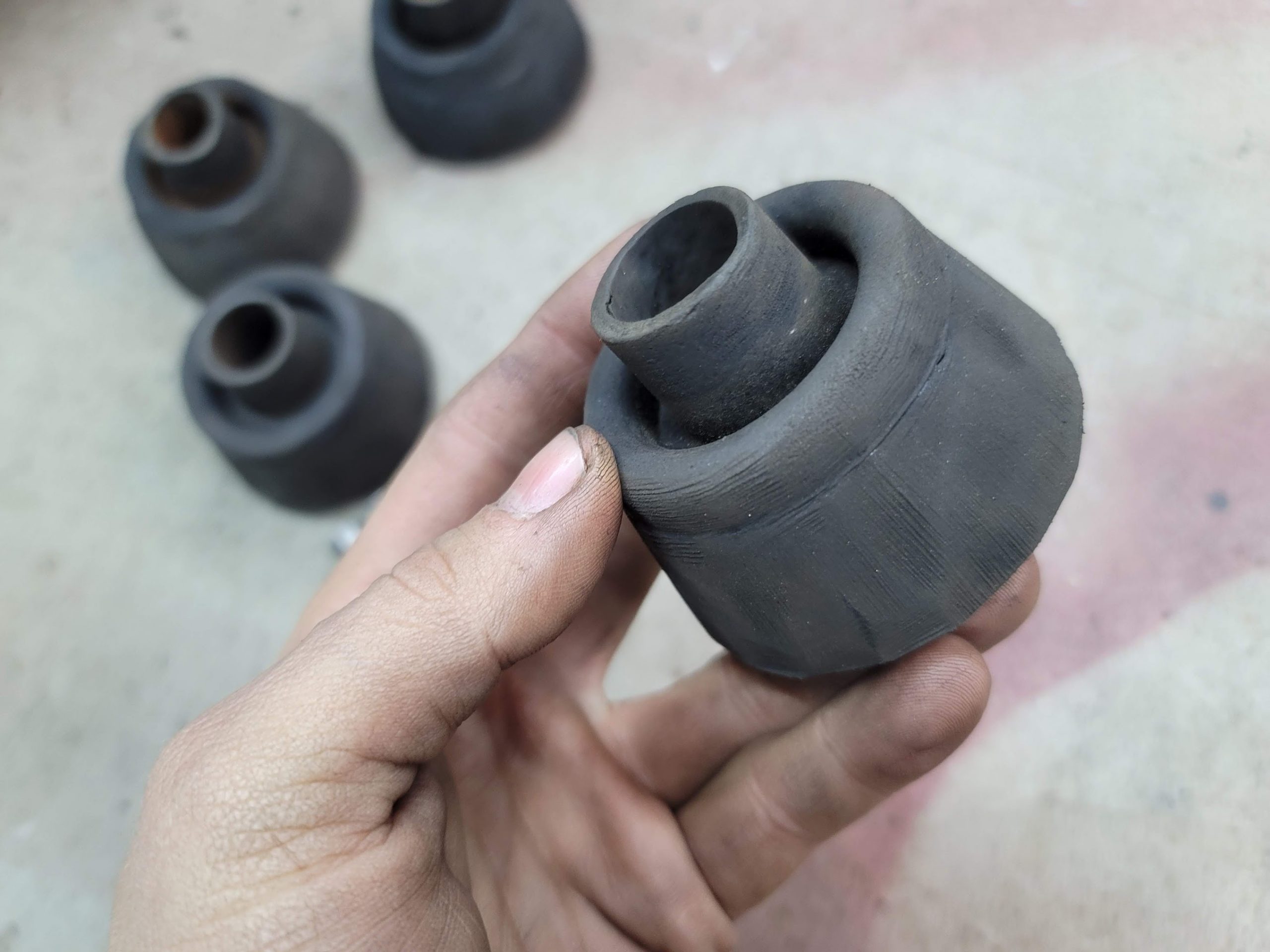
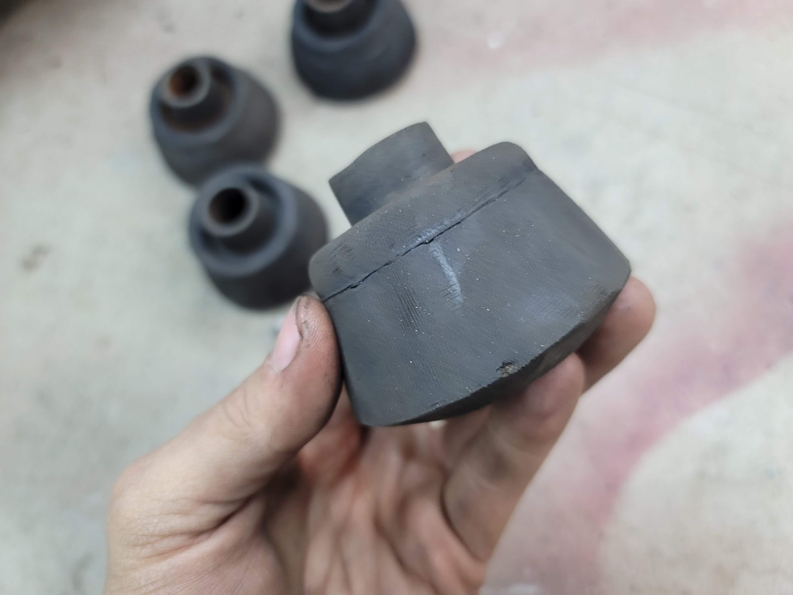
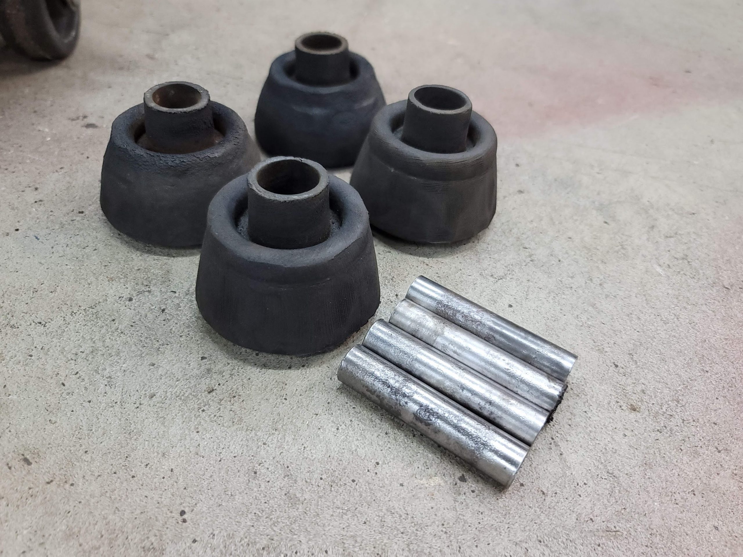
Next I took a stab at cleaning up the old rubber feet, this did not go so great, but at least they are ‘clean’ of all the old oil and funk now.
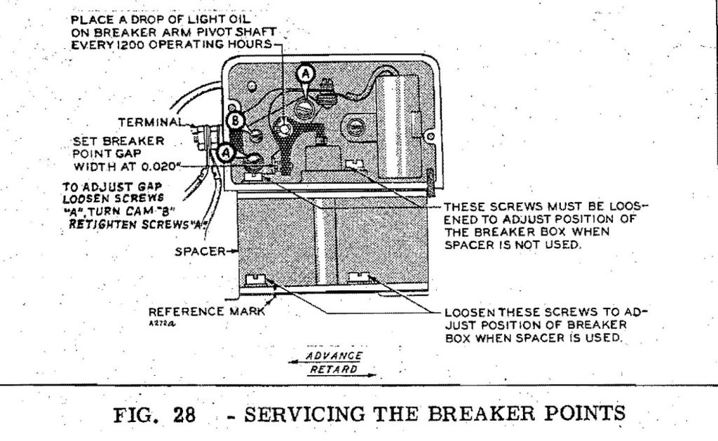
Now to get everything ready for testing. I also took the time to replace the condenser and cleaned the points.
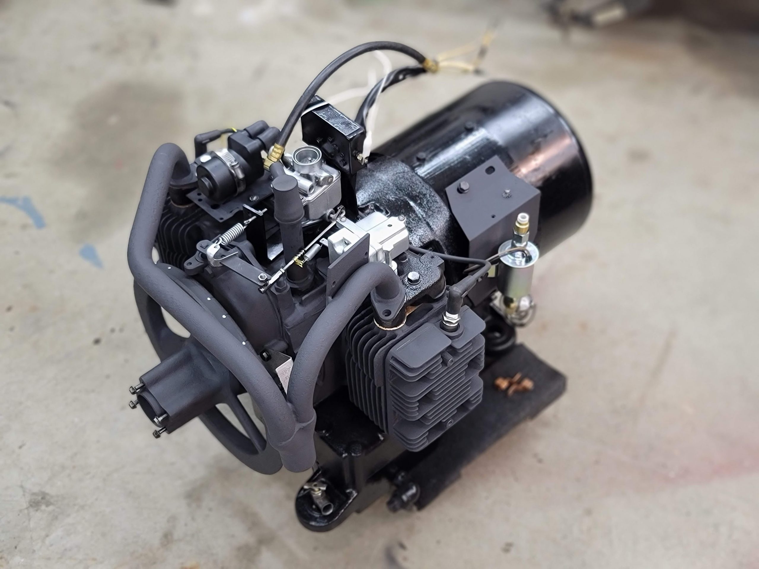
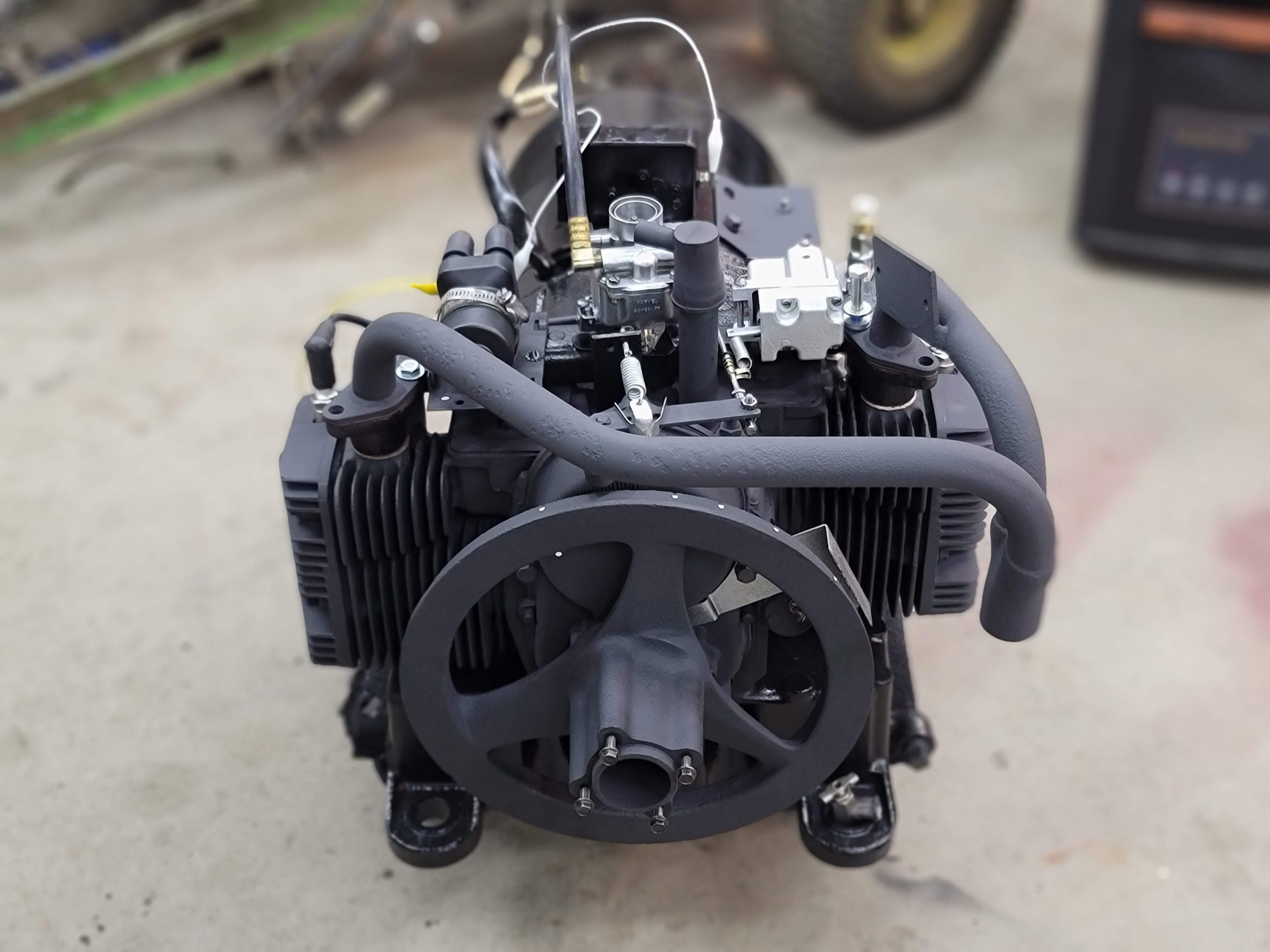
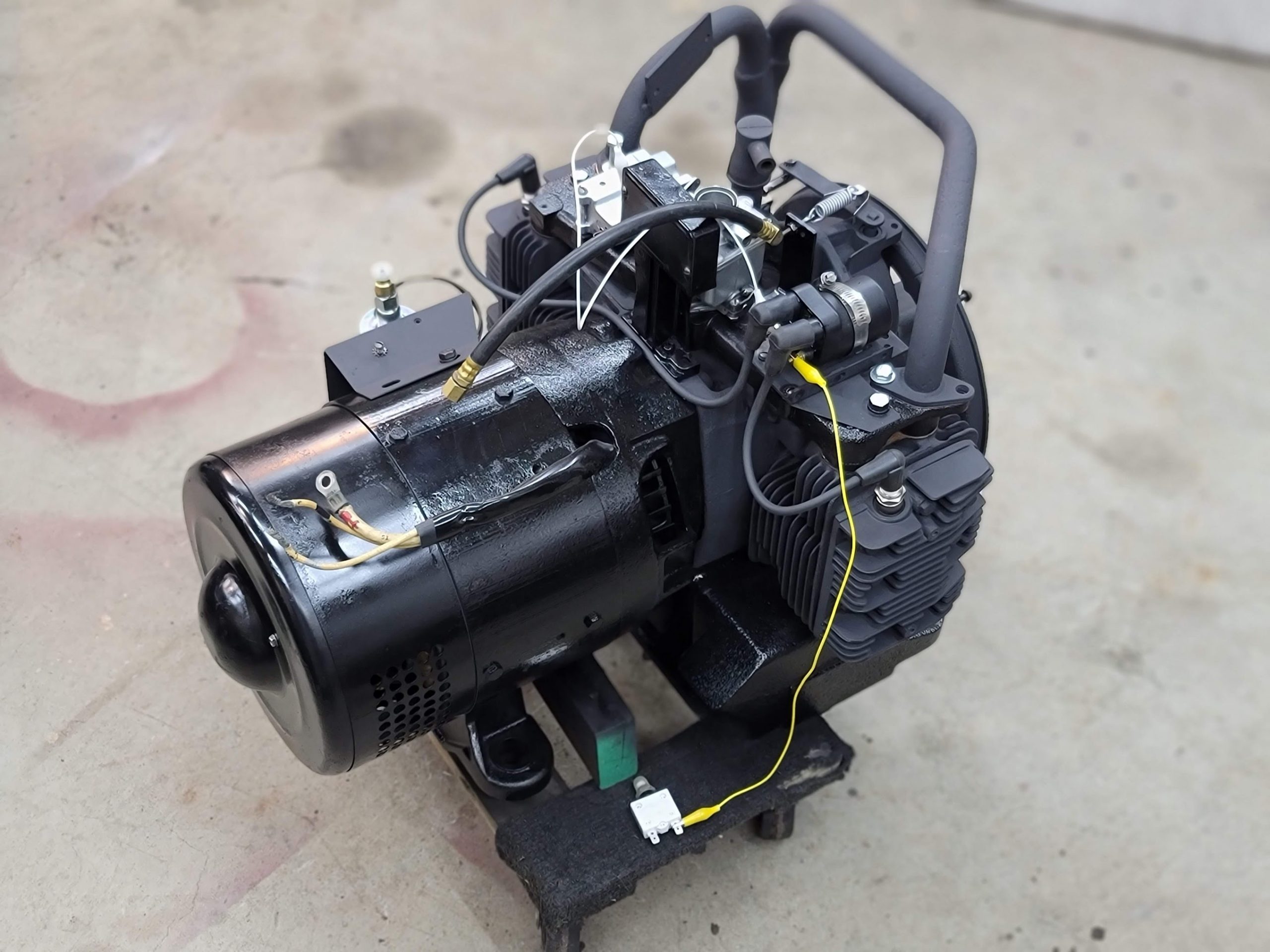
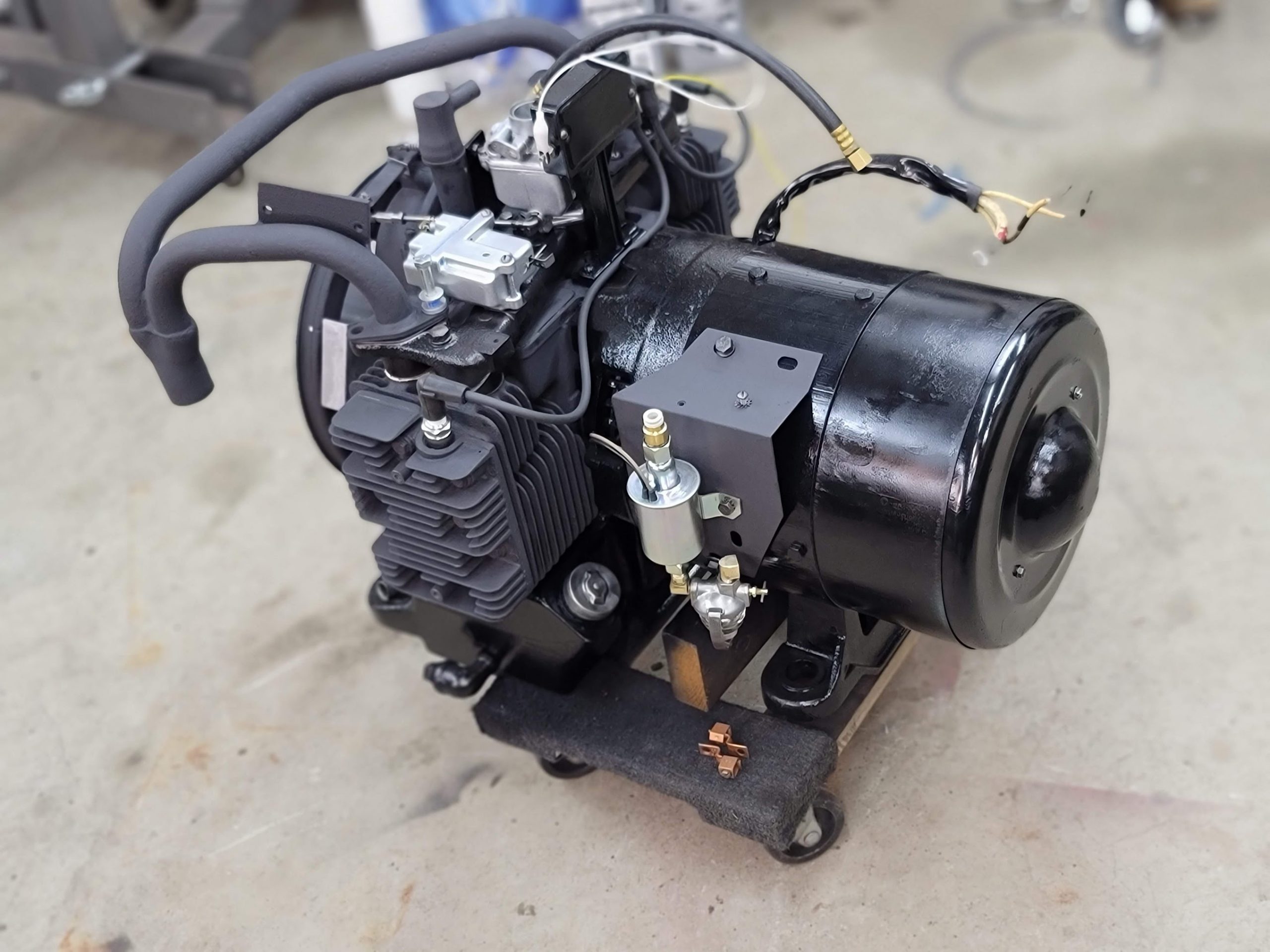
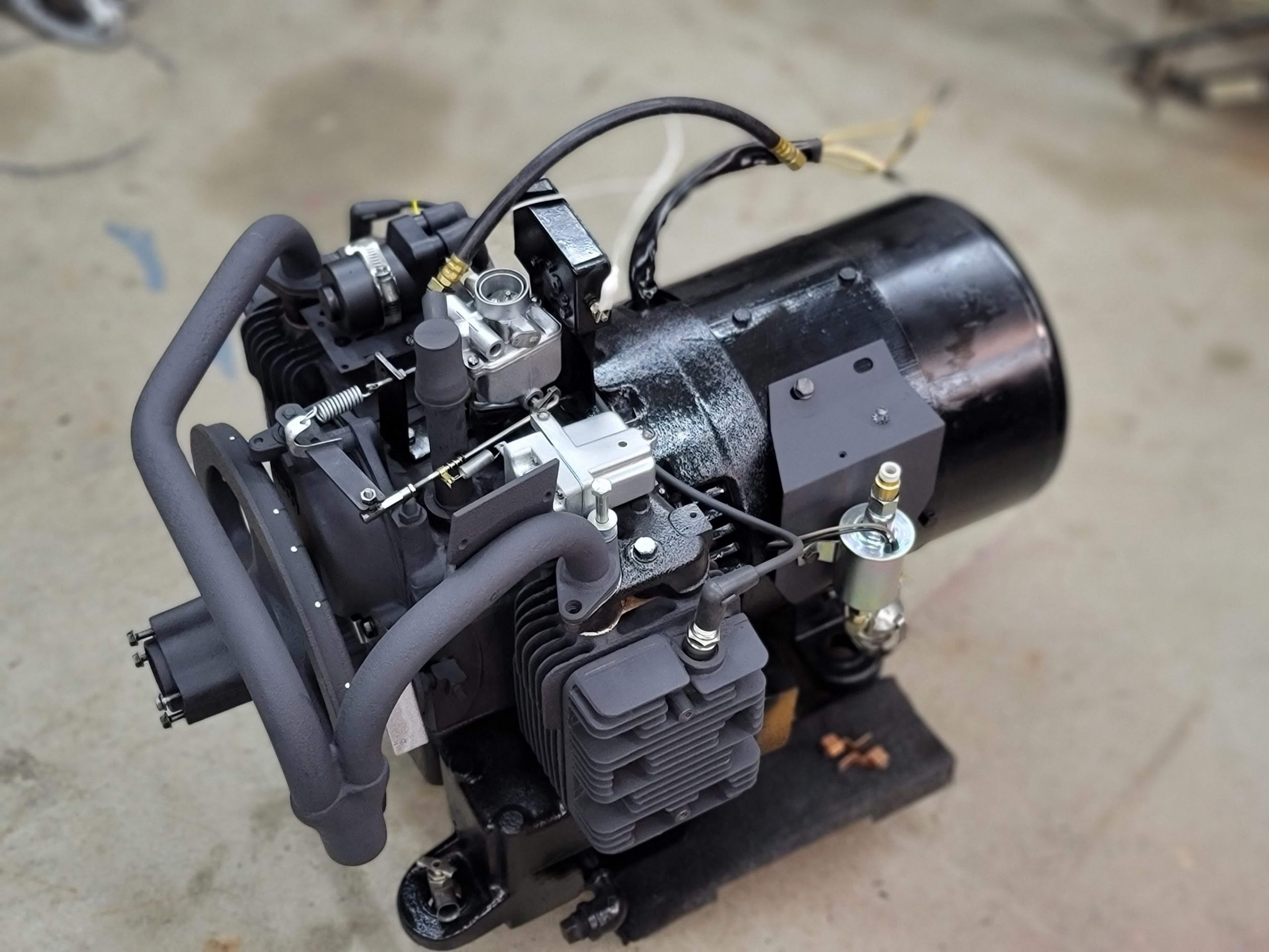
I need to head to the store to buy some new exhaust bolts, with all the snow here that makes it an adventure. I have some temp ones in place now as placeholders. The exhaust was pretty pitted, but still looks much better. … Ah yes testing… I need to make sure I ease into the motor,
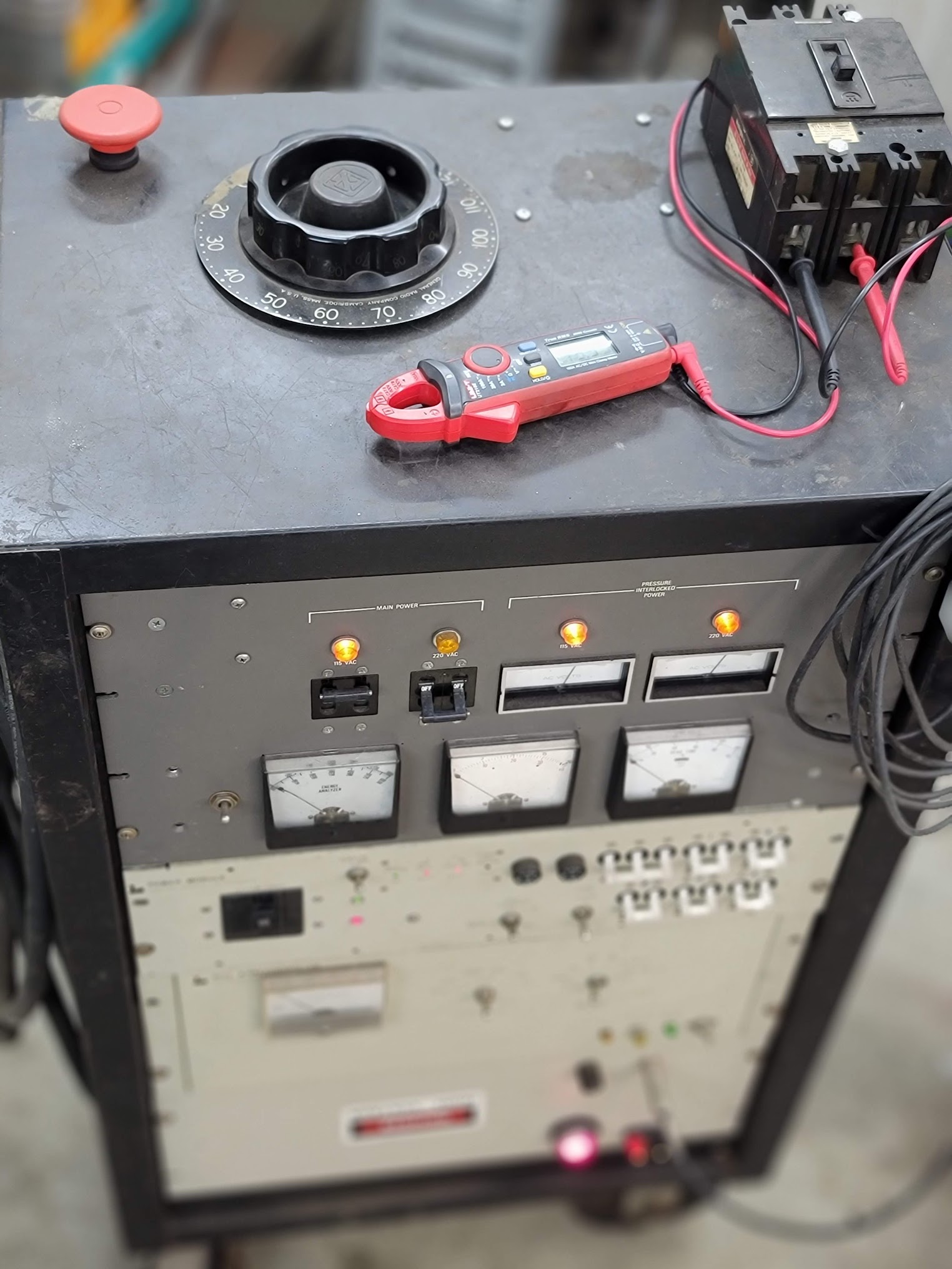
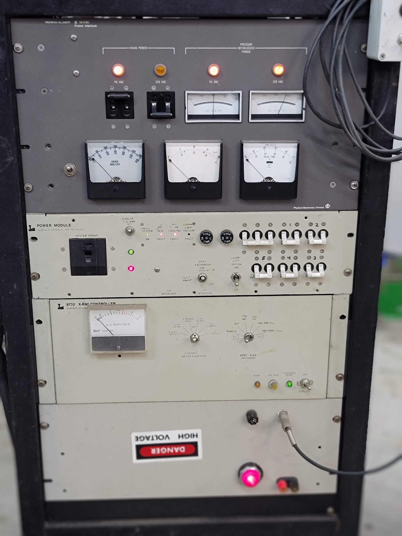
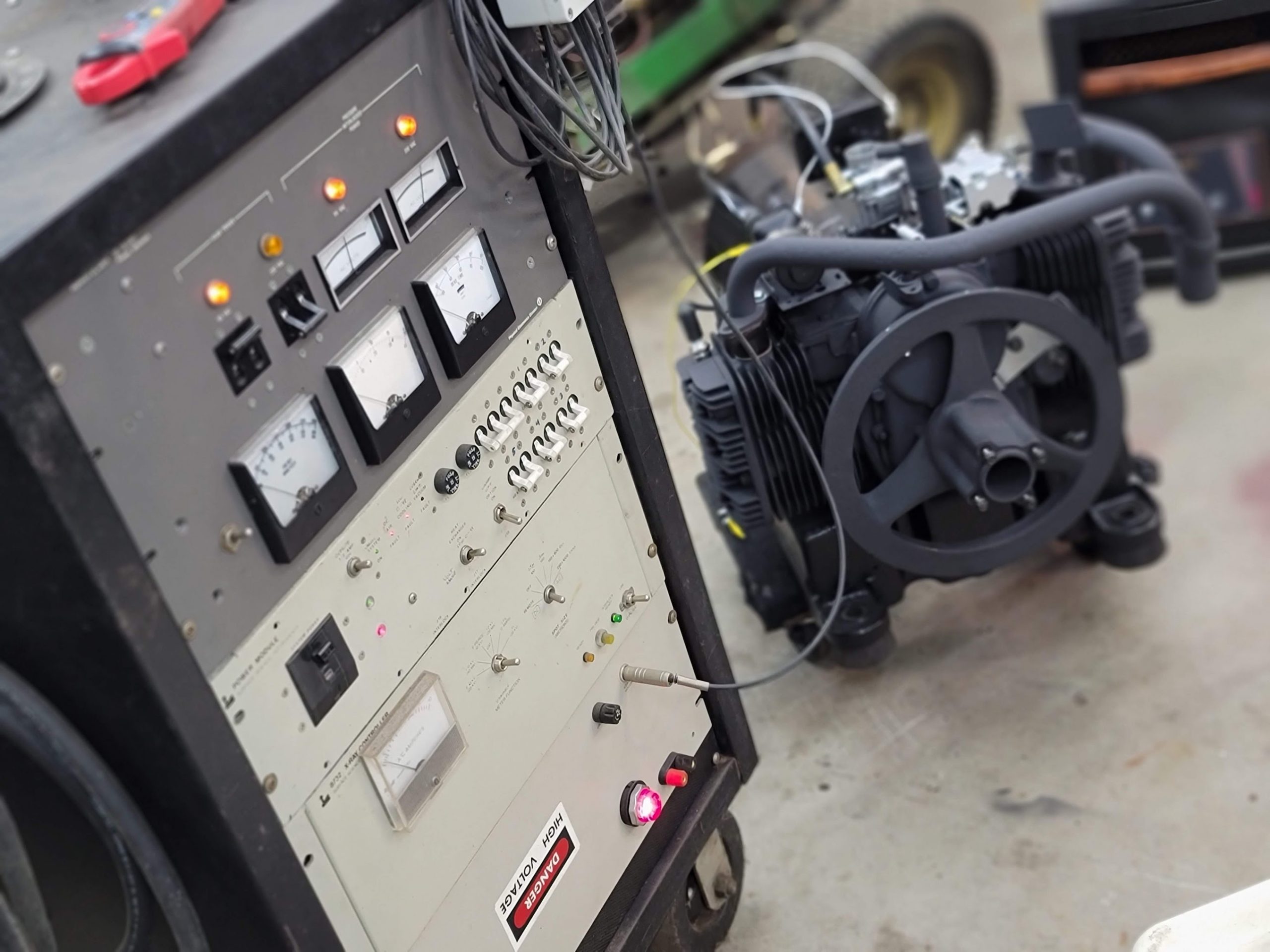
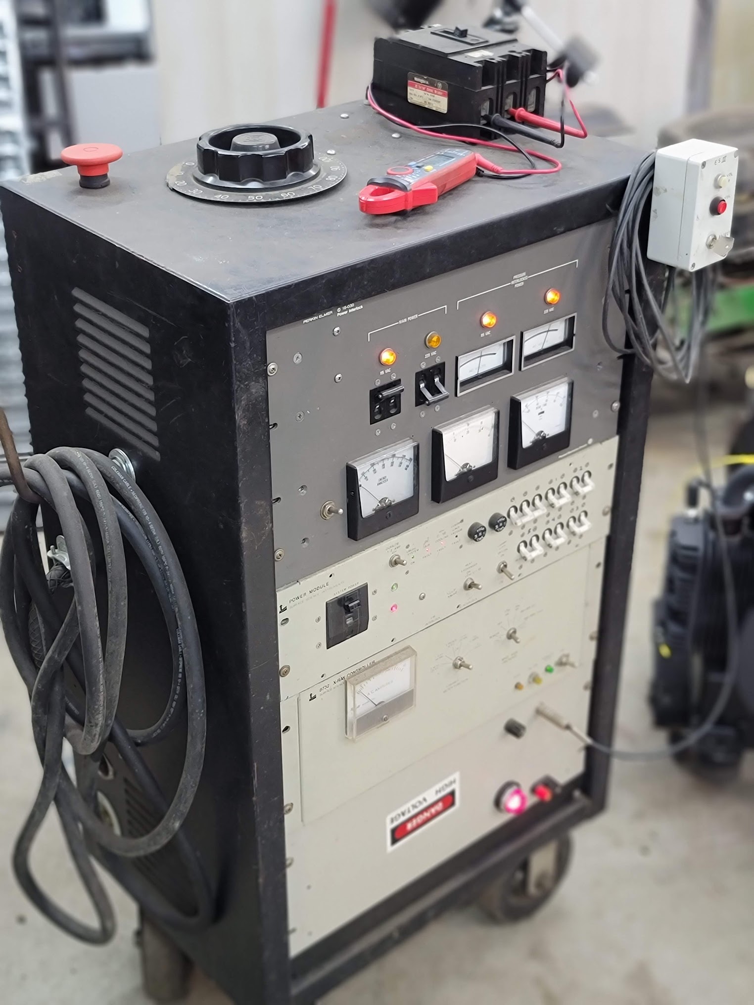
This is the lab, so you know I can not do anything ‘normal’ like just slap a battery on it and go for it.
I am using my massive 250lbs DIY power supply, this will give me precise control over the startup, and allow me to monitor currents and voltages. I am looking for anything I may have miswired in the brush end, or any shorted components. before a battery will let the magic smoke out ha!
Updates soon if everything checks out! -2F outside right now, so a bit too cold for fiddly work.
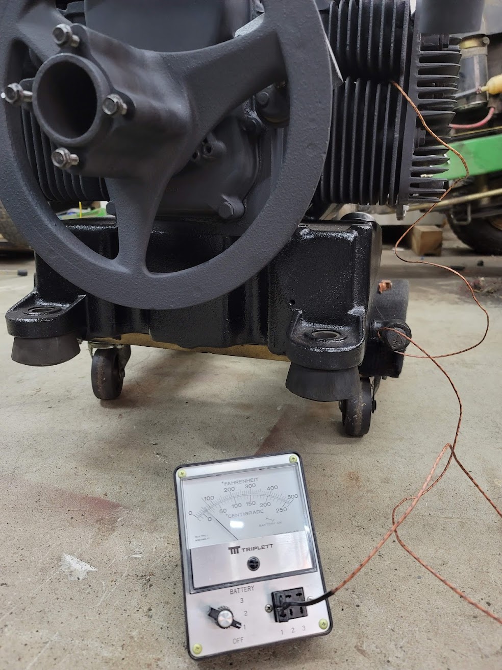
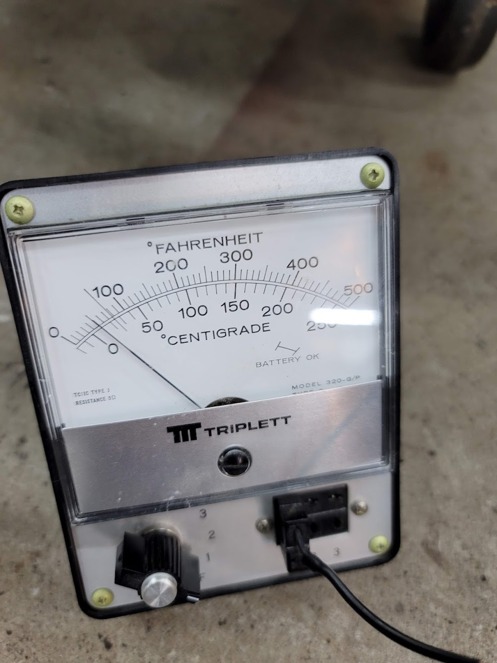
Setup a Type K thermocouple to monitor head temps, being that I will be test running it with no air ducting to keep things cool. Don’t want to cook it!
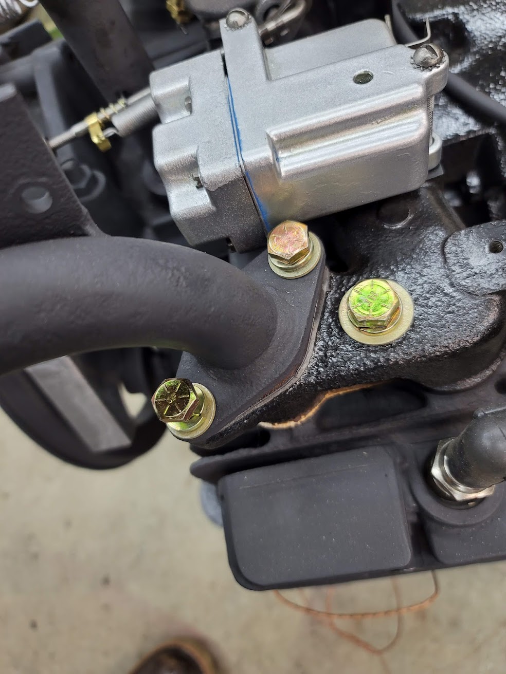
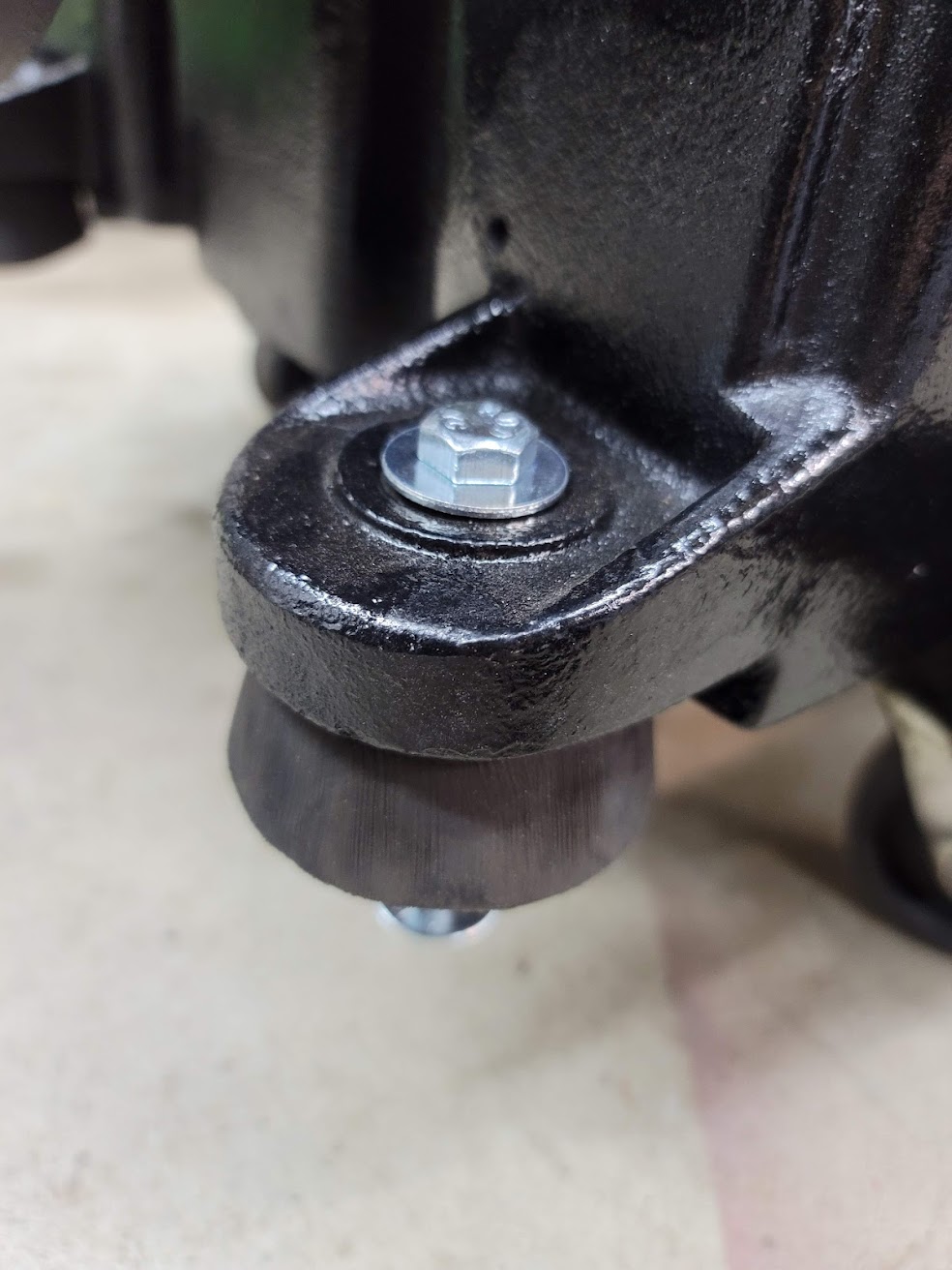
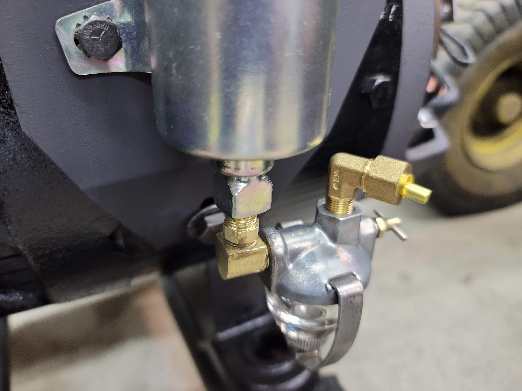
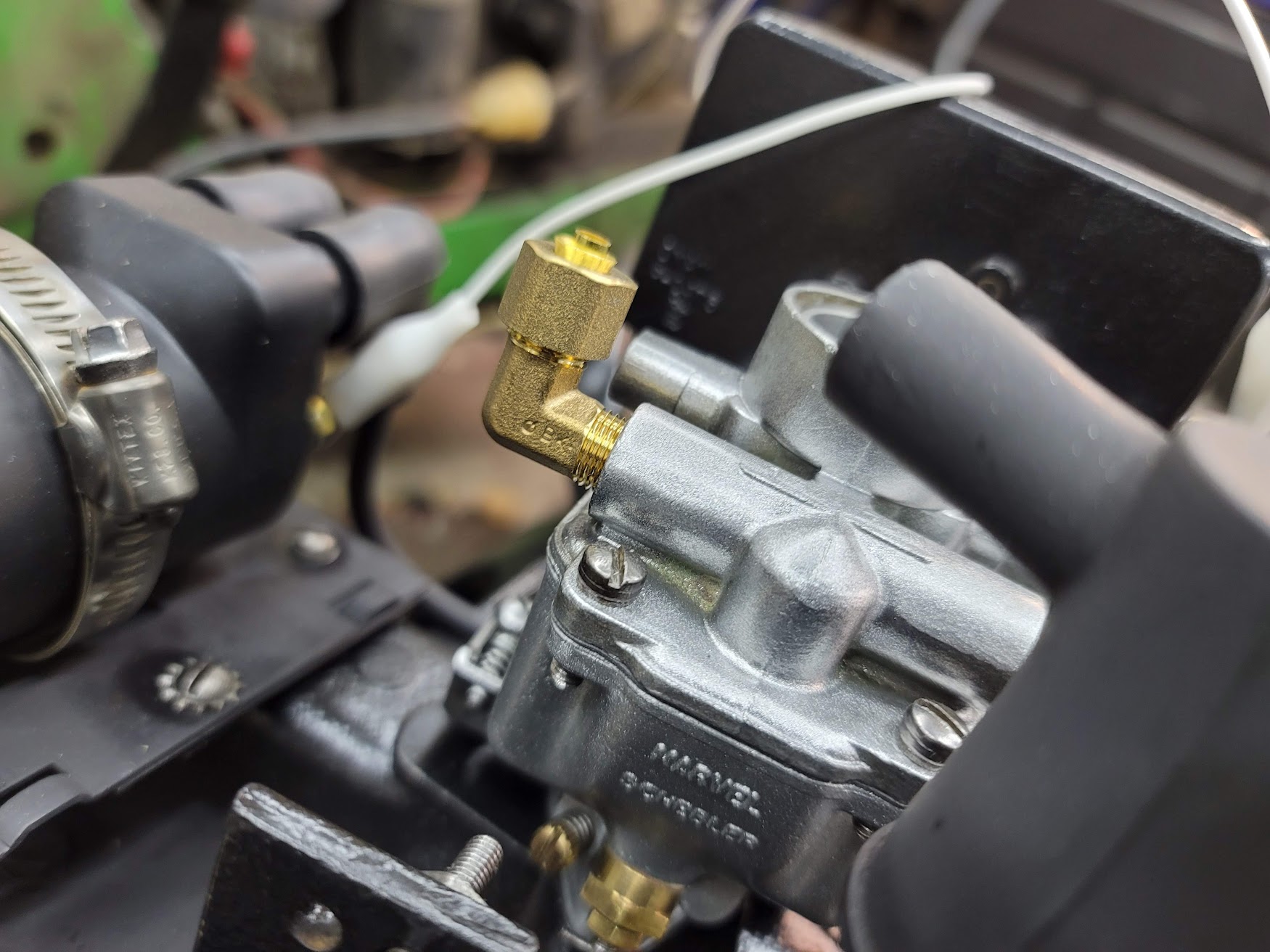
Order of new hardware and fittings came in. Makes for a nice improvement. Was also able to clean up the old rubber foot mounts. Next step is to get the battery leads wired up.
UPDATE: 2/3/2022 Fuel system plumbed up and tested, no leaks, and fuel pump works!
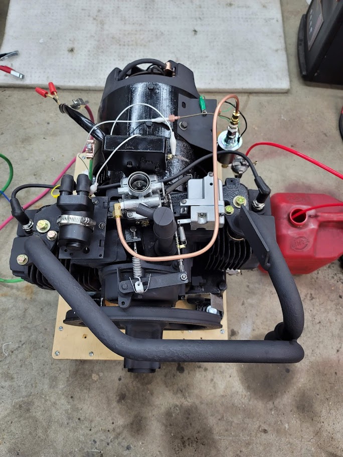
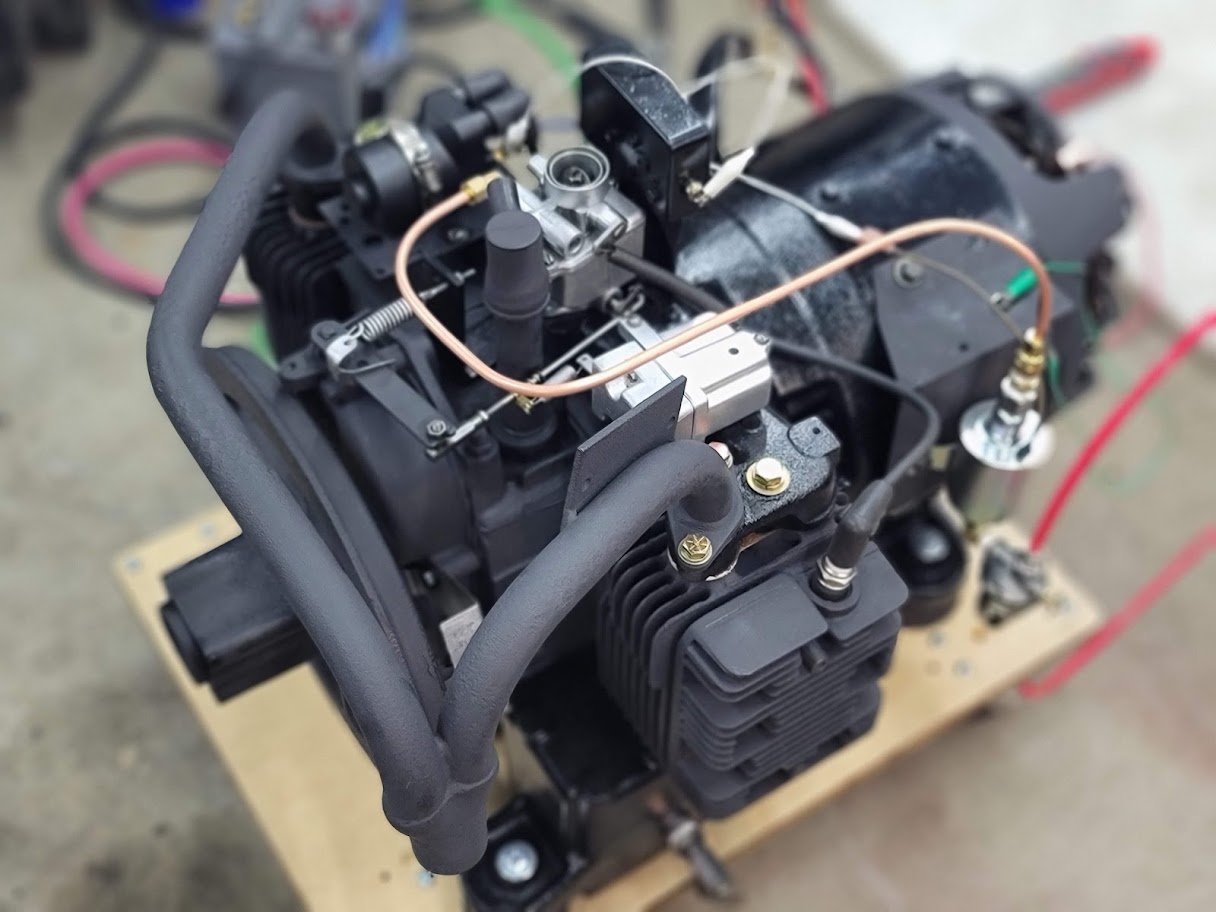
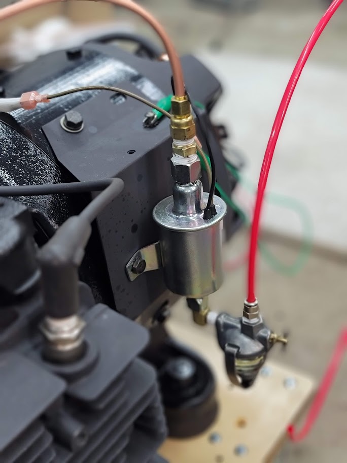
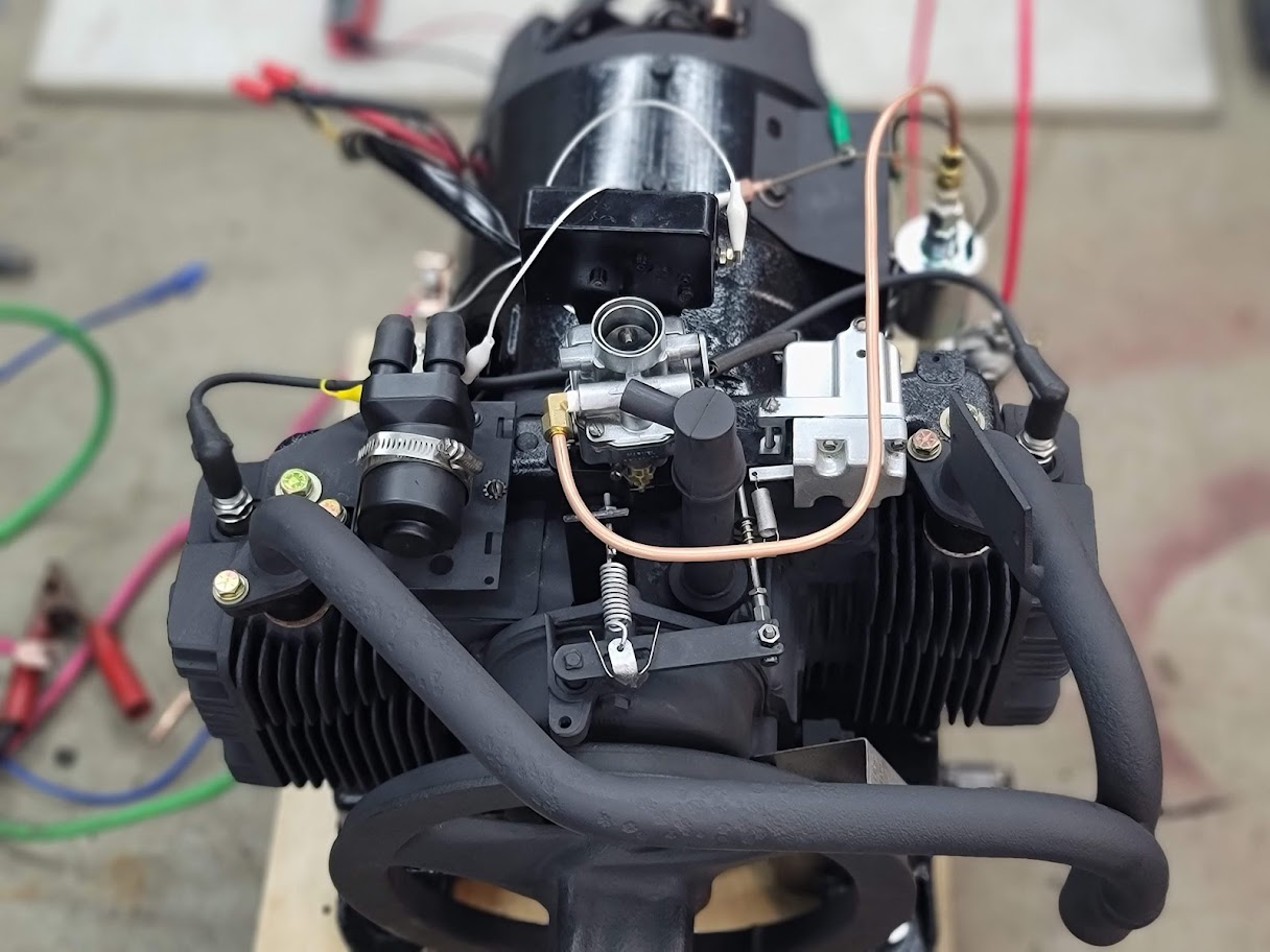
Next step, get some gas and see if she runs!
She runs! Sadly needs about 70% choke to stay running, super lean. Carb needs tuned. Expected so doing a full rebuild. Also checked output, was getting 150VAC so running a bit fast as well. Next will be some fuel mixture adjustments, and governor adjustments.
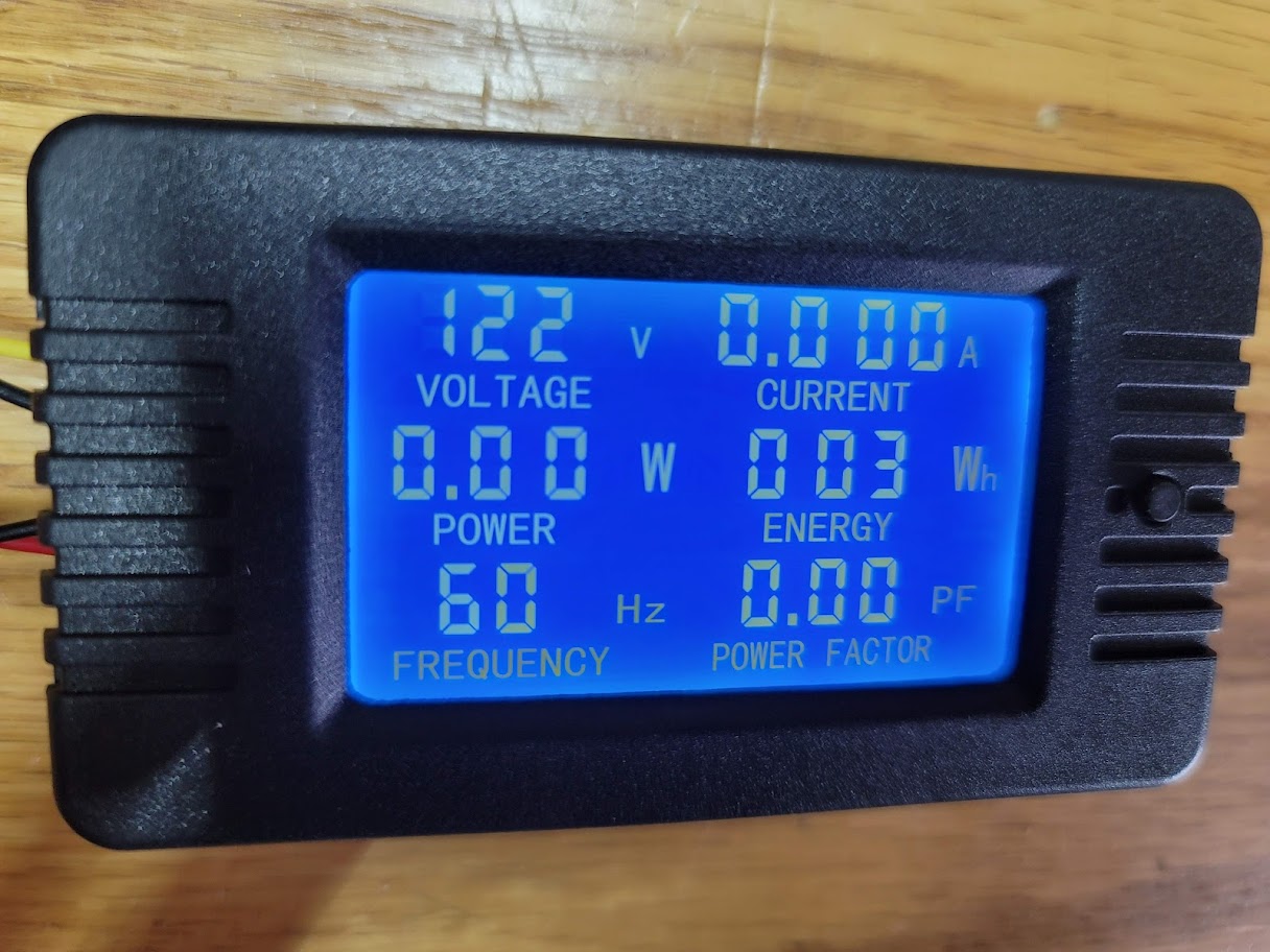
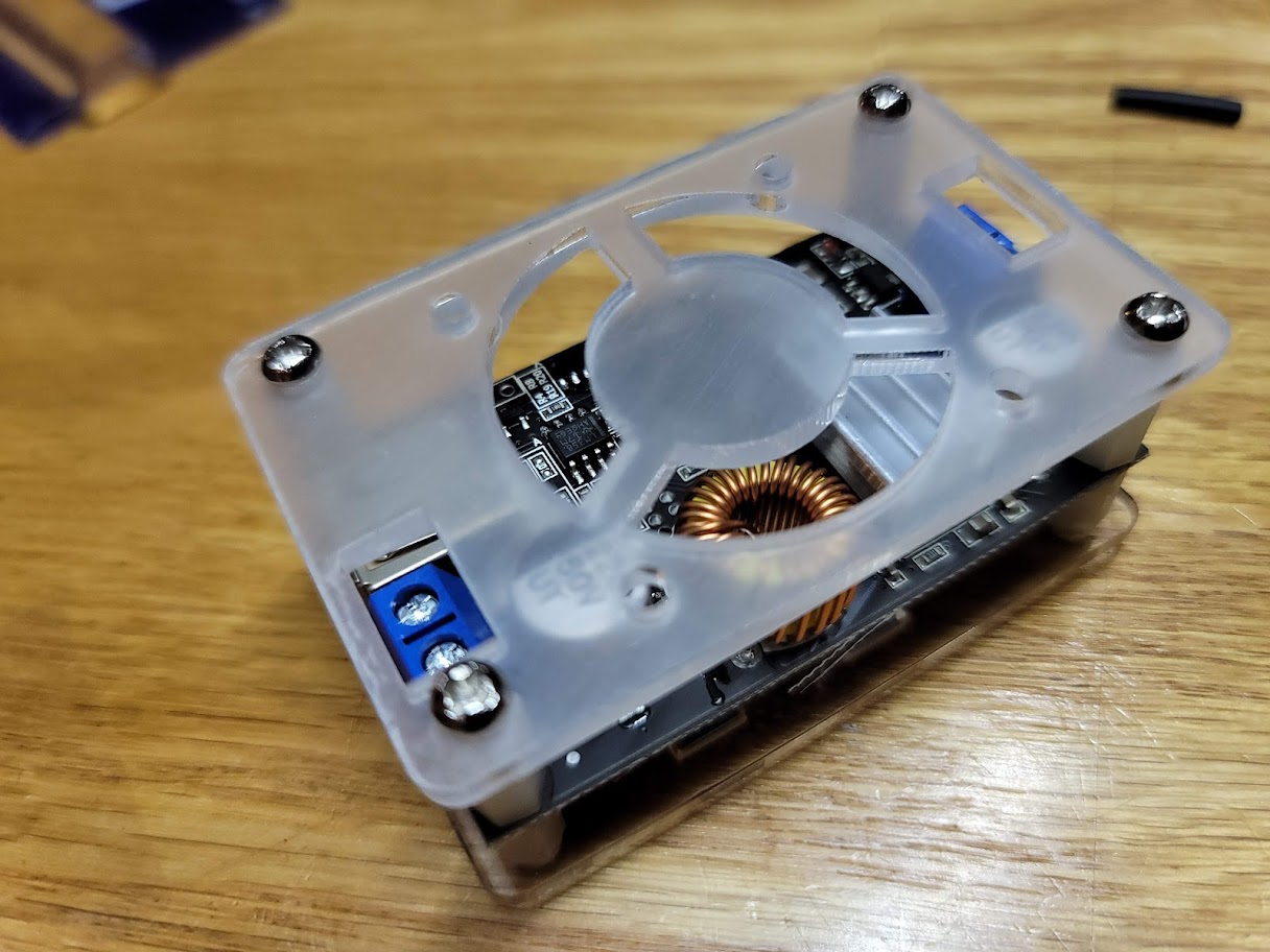
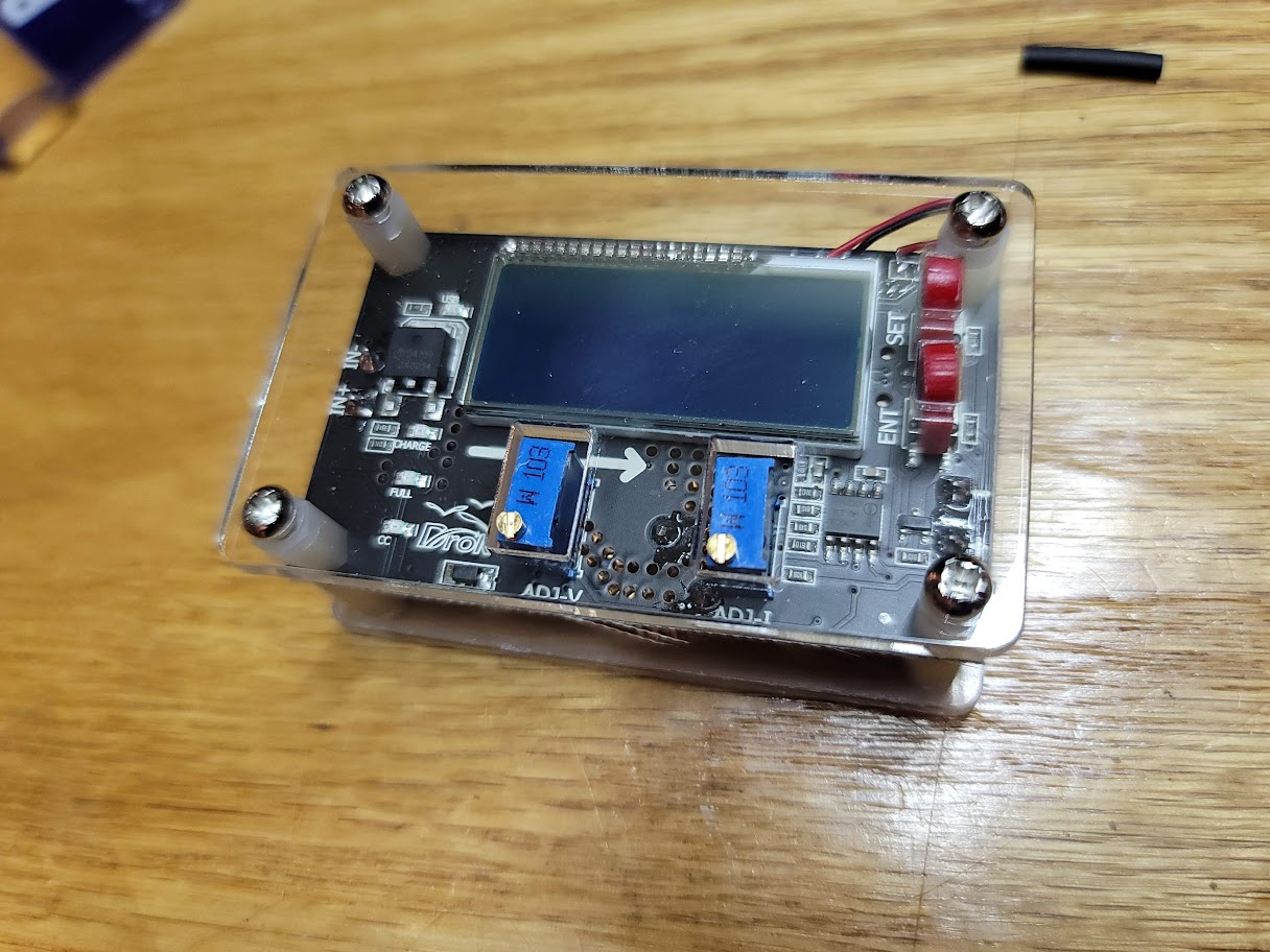
Picked up these two units, the Blue one is a digital gauge that will measure everything you would want with a generator output. The clear one is a DC to DC buck converter for taking the ~17VDC from the DC side output and convert it to 13.8VDC to charge the battery and run the ignition system.
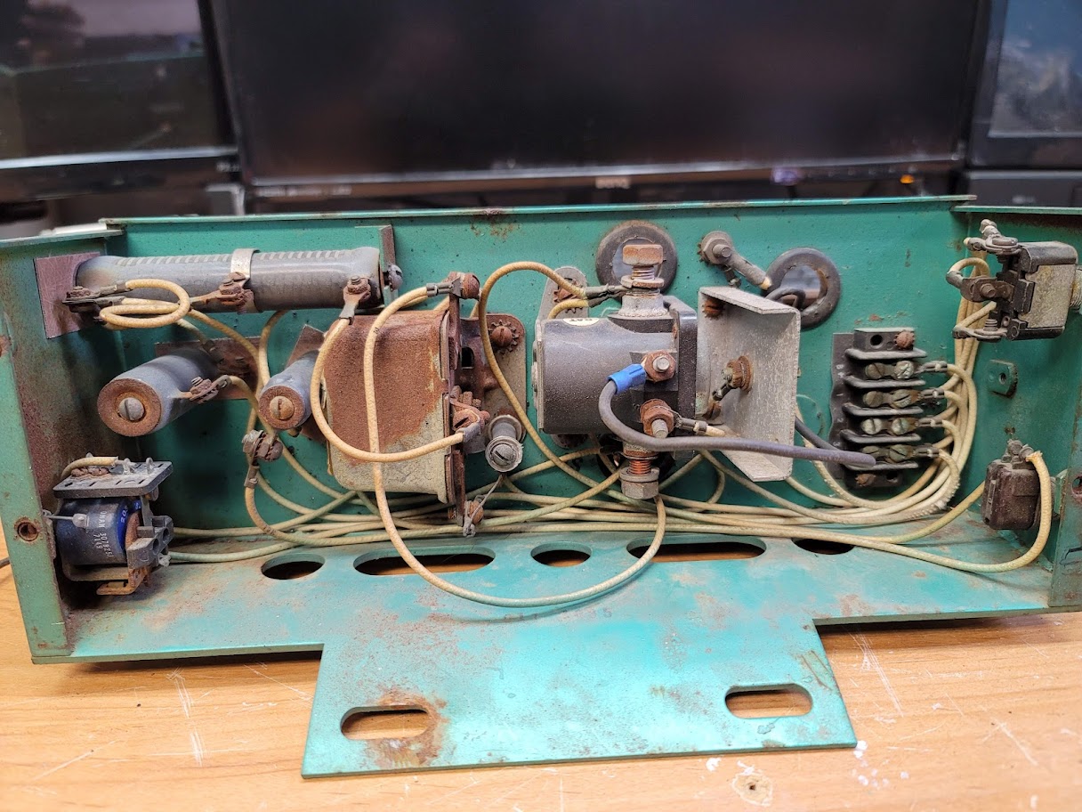
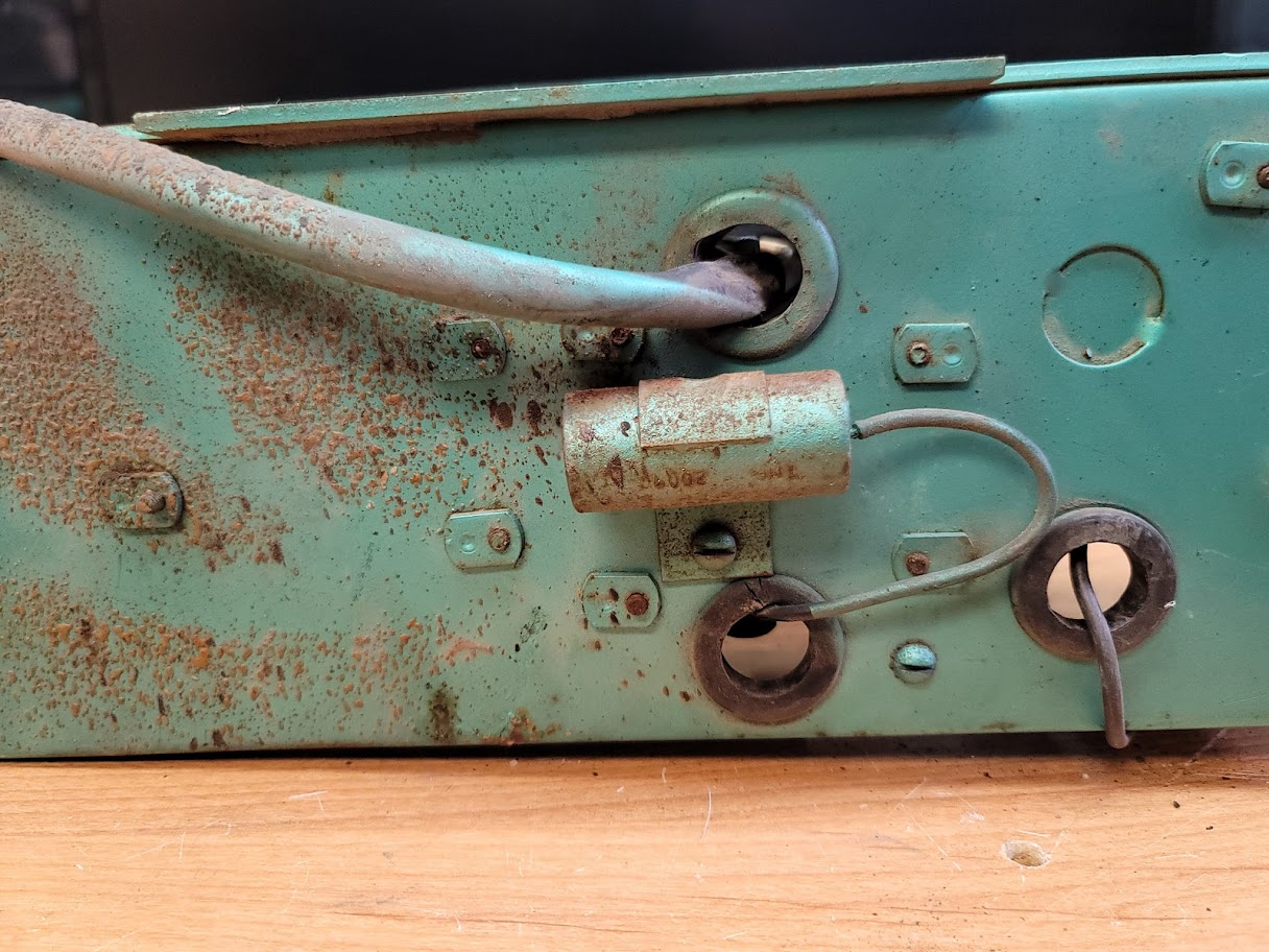
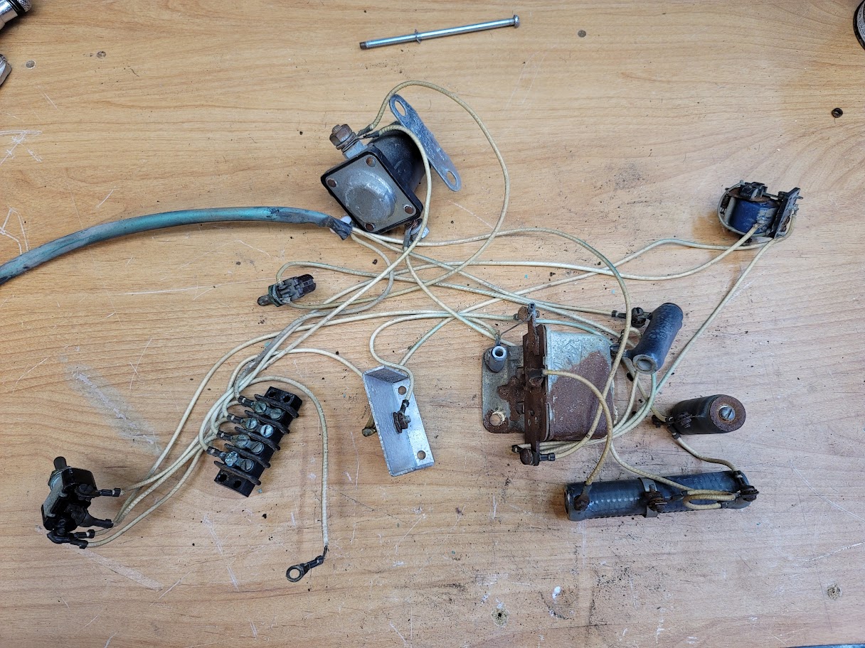
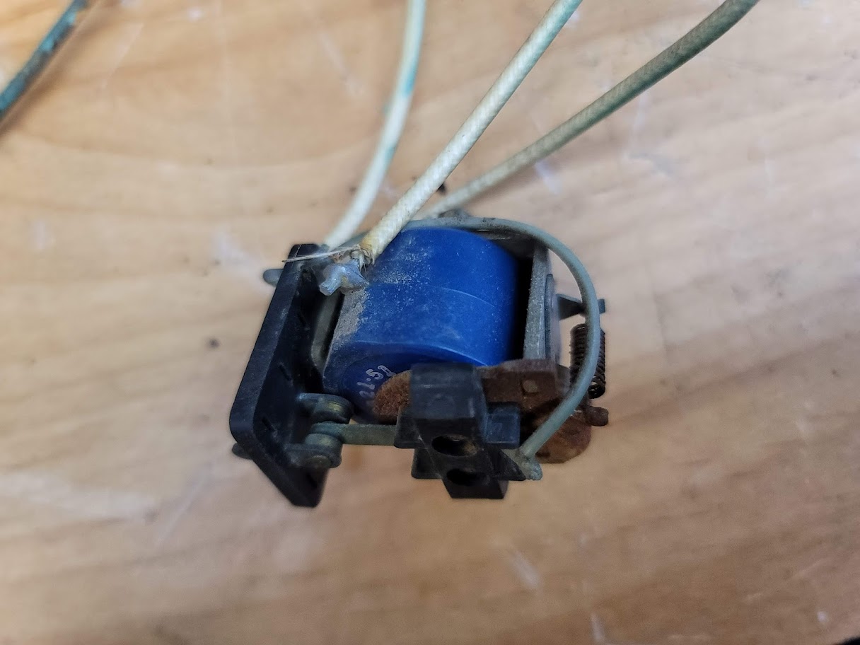
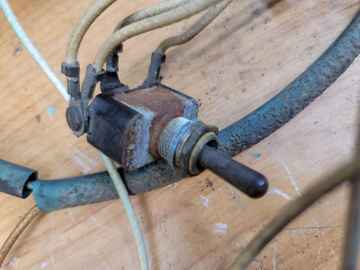
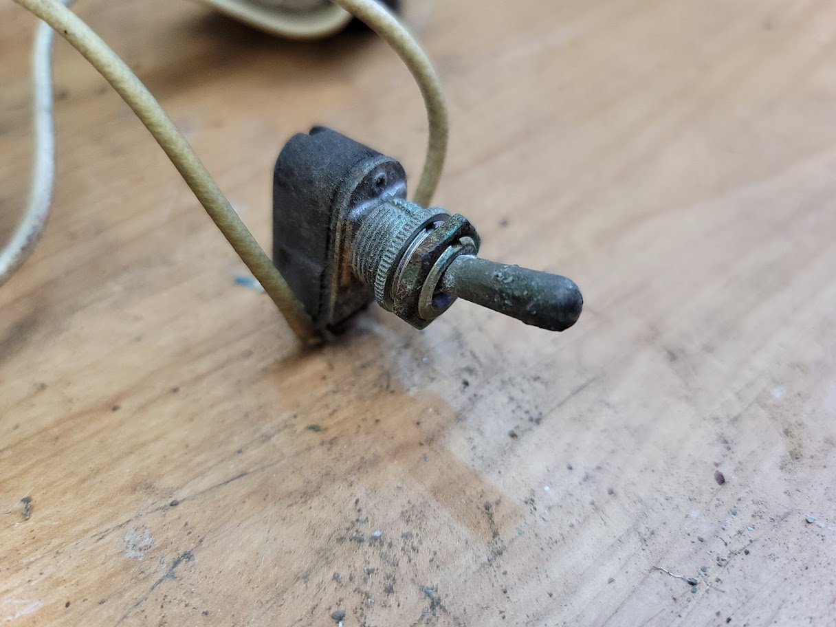
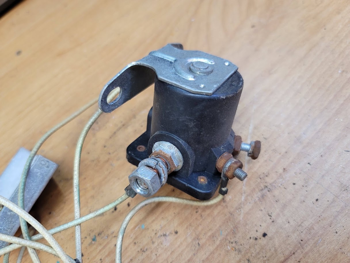
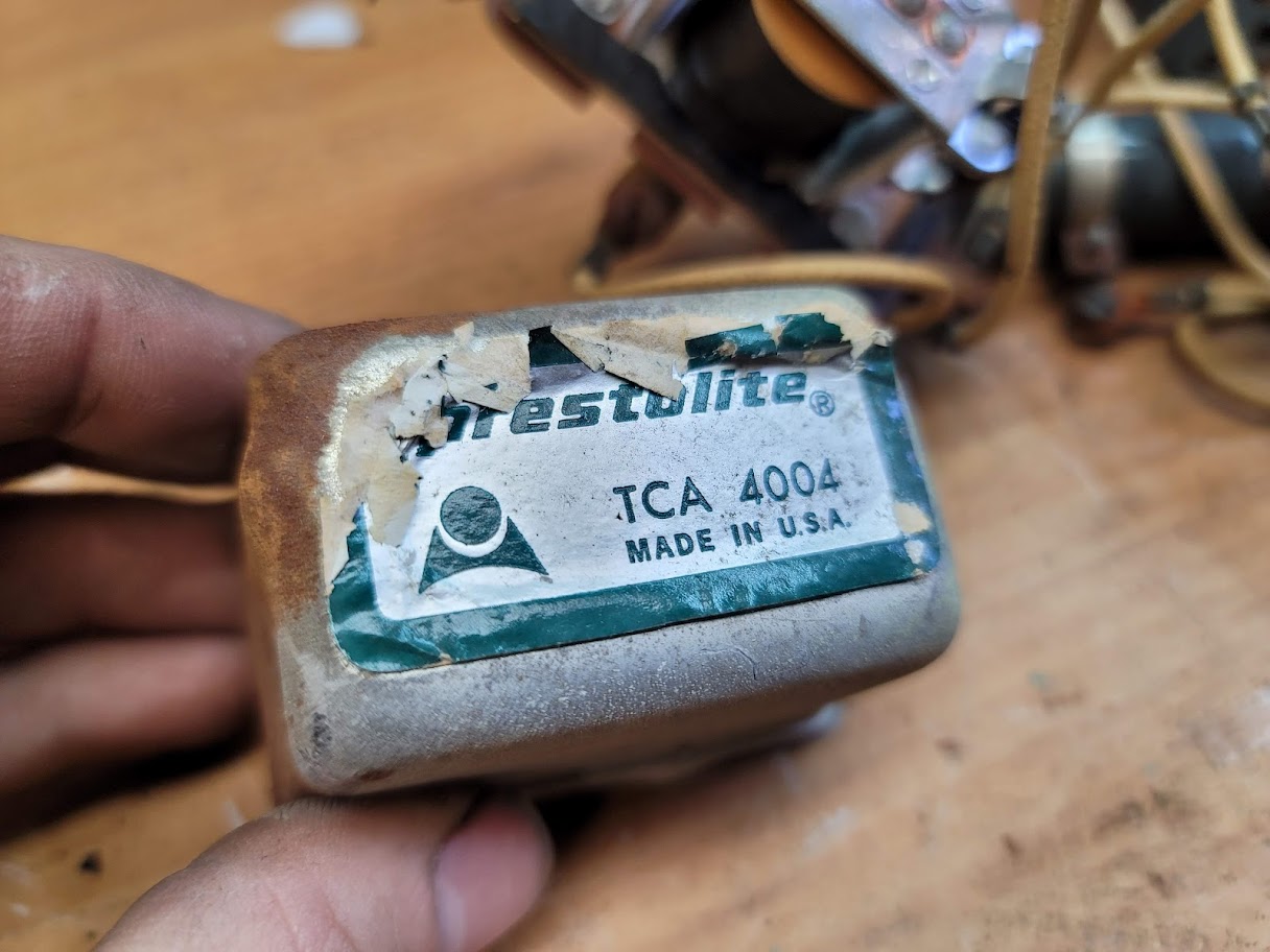
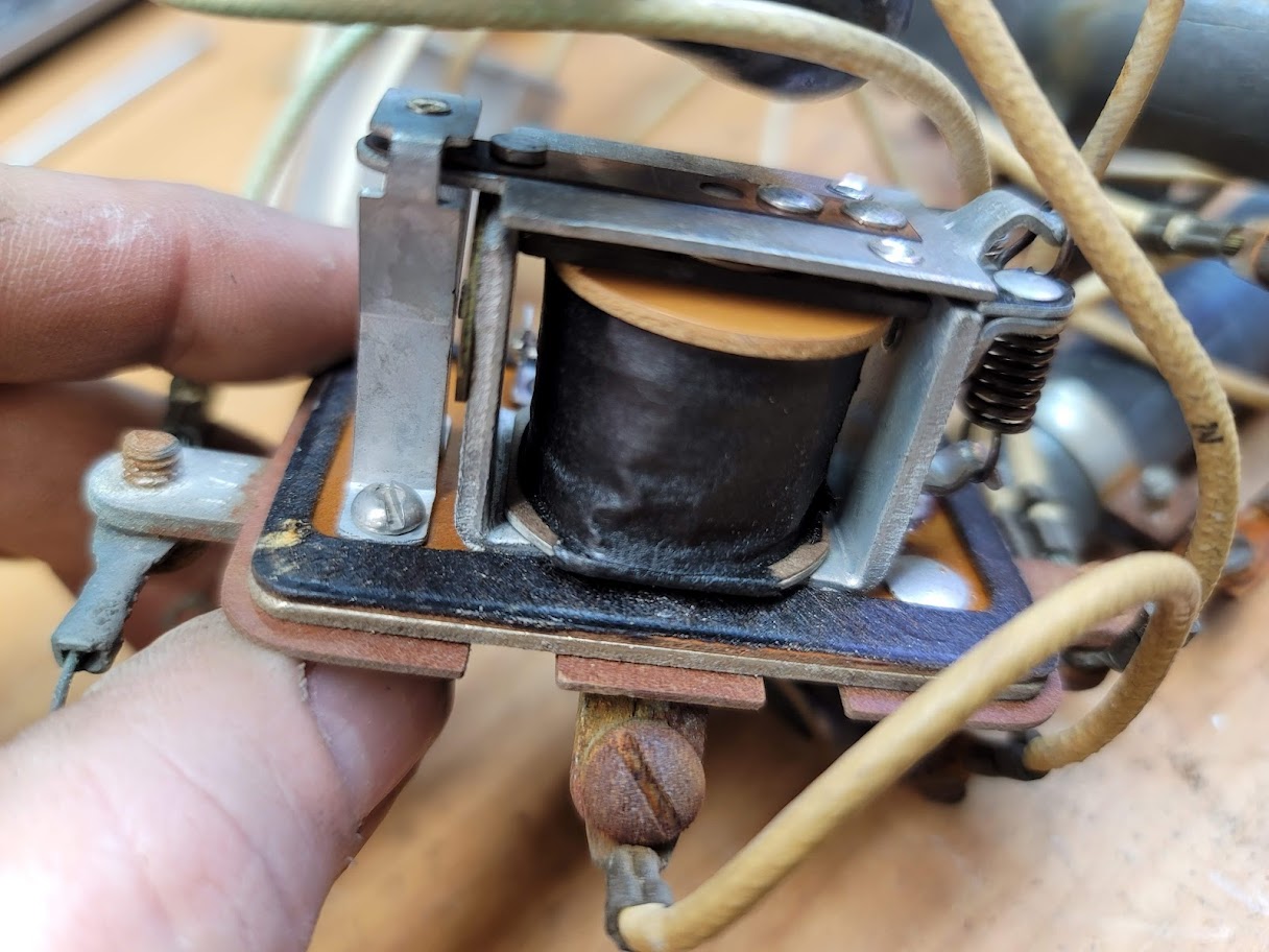
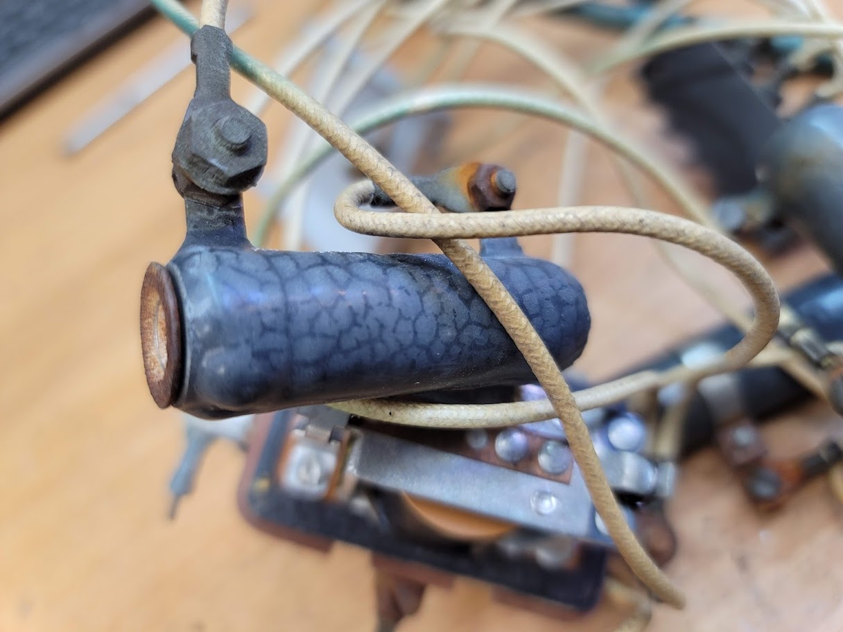
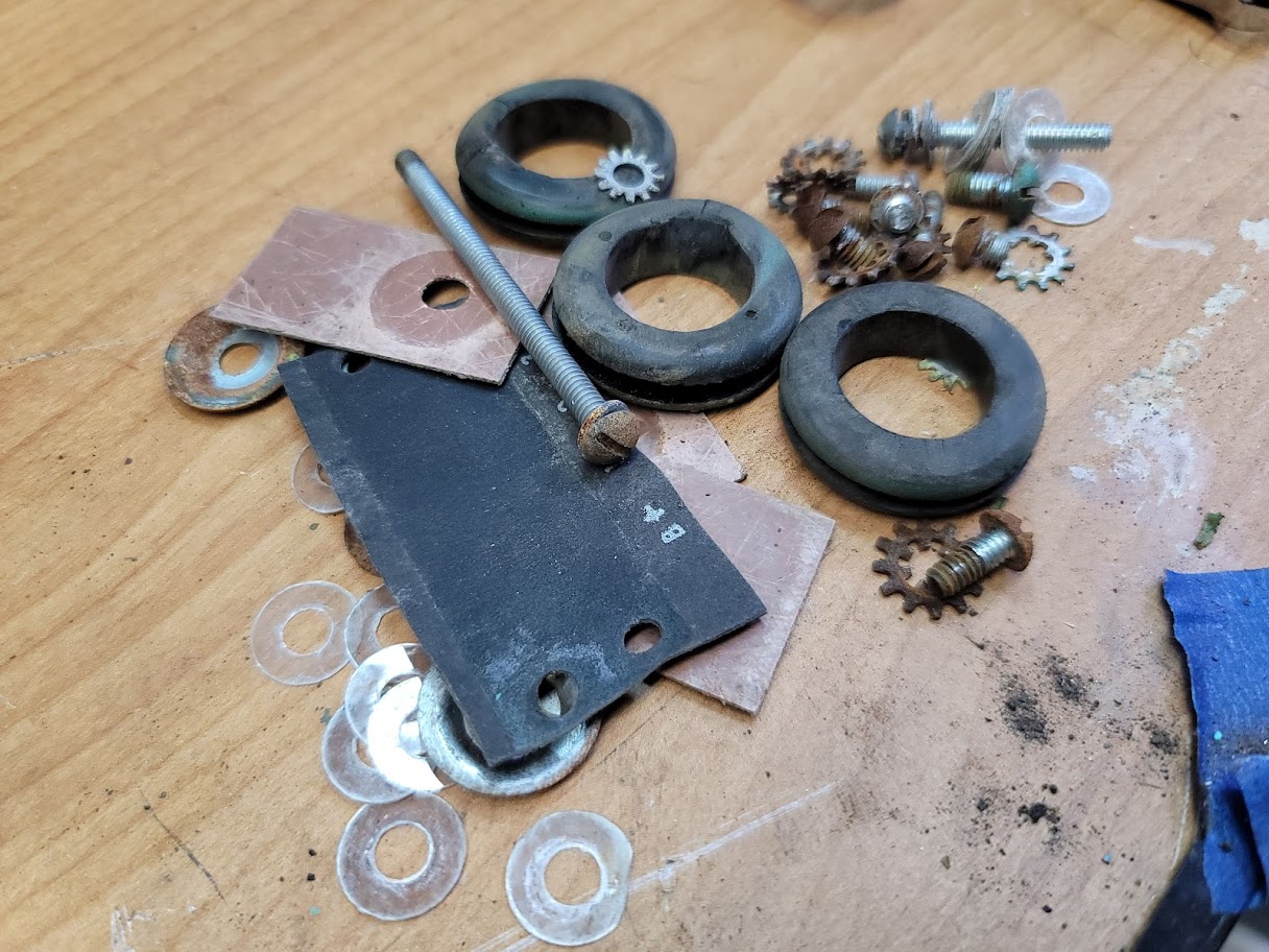
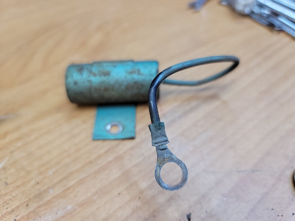
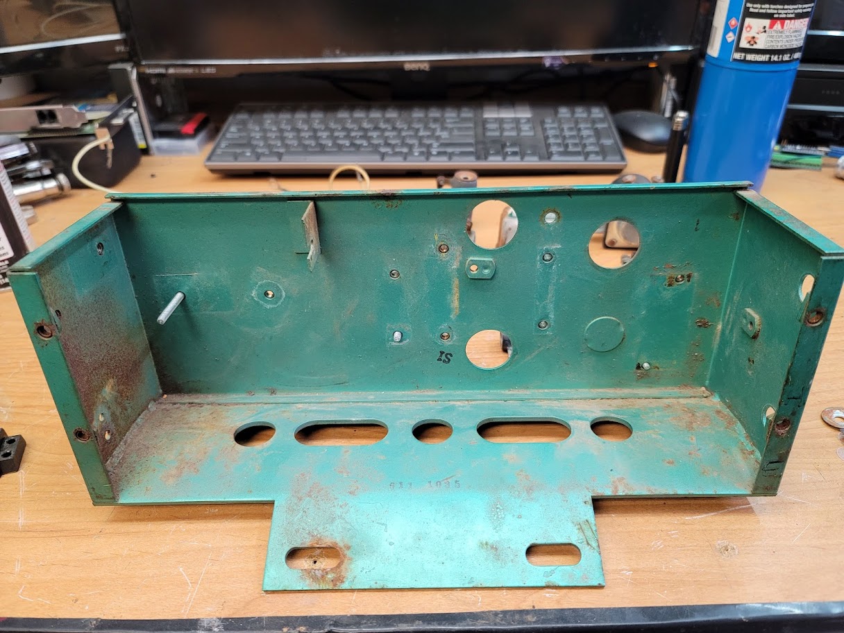
Speaking of electronics, I pulled all the old power components, Tested and cleaned them, looks like the resistors may be shot, and the Run/stop relay is shot. Going to clean up the old chassis, and start designing a new cover to replace the missing one. Will take this time to find out how to fit the new electronics.
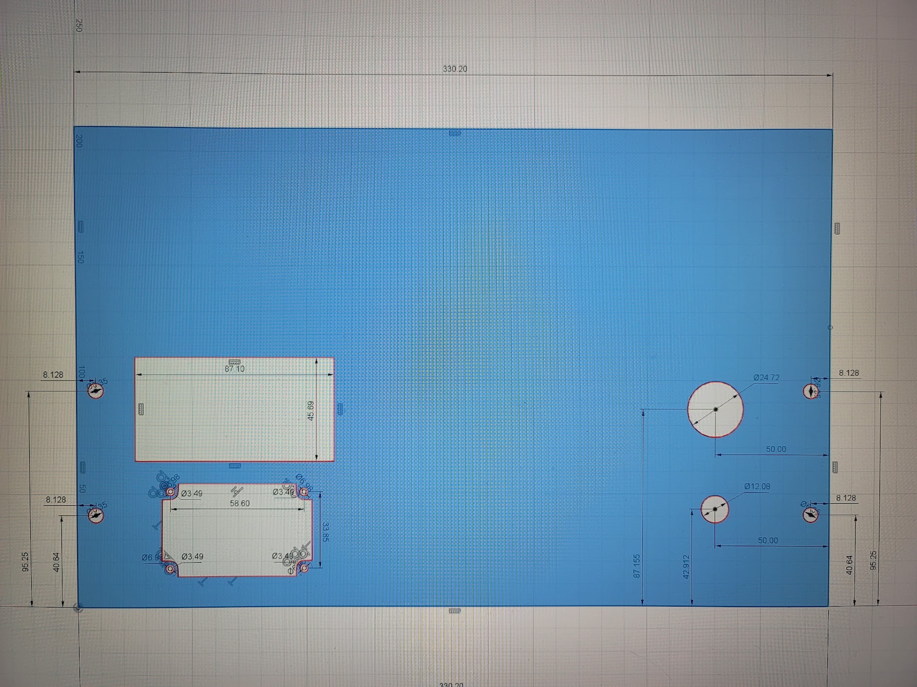
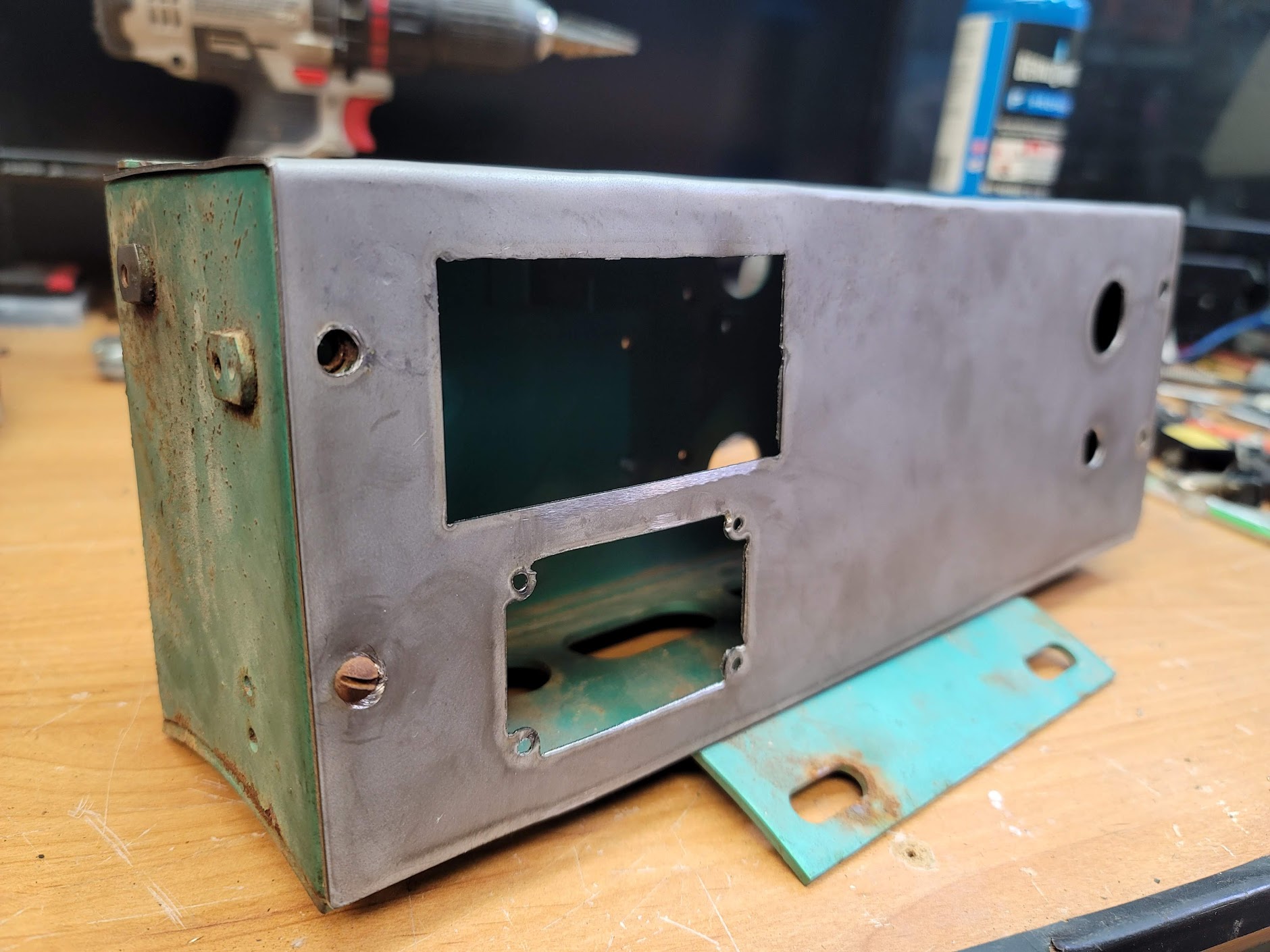
UPDATE: 2/5/2022 Wired in the new control box!
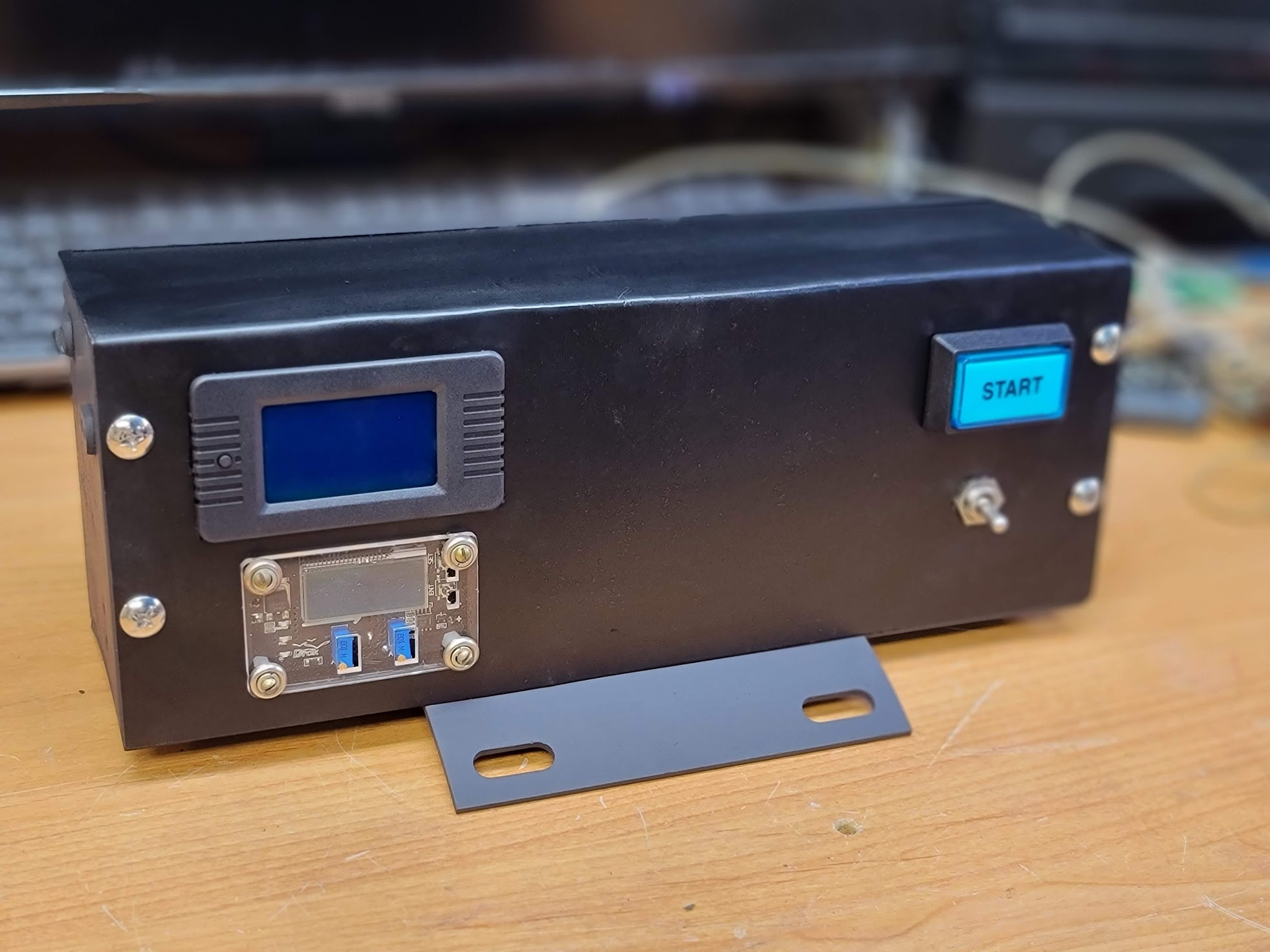
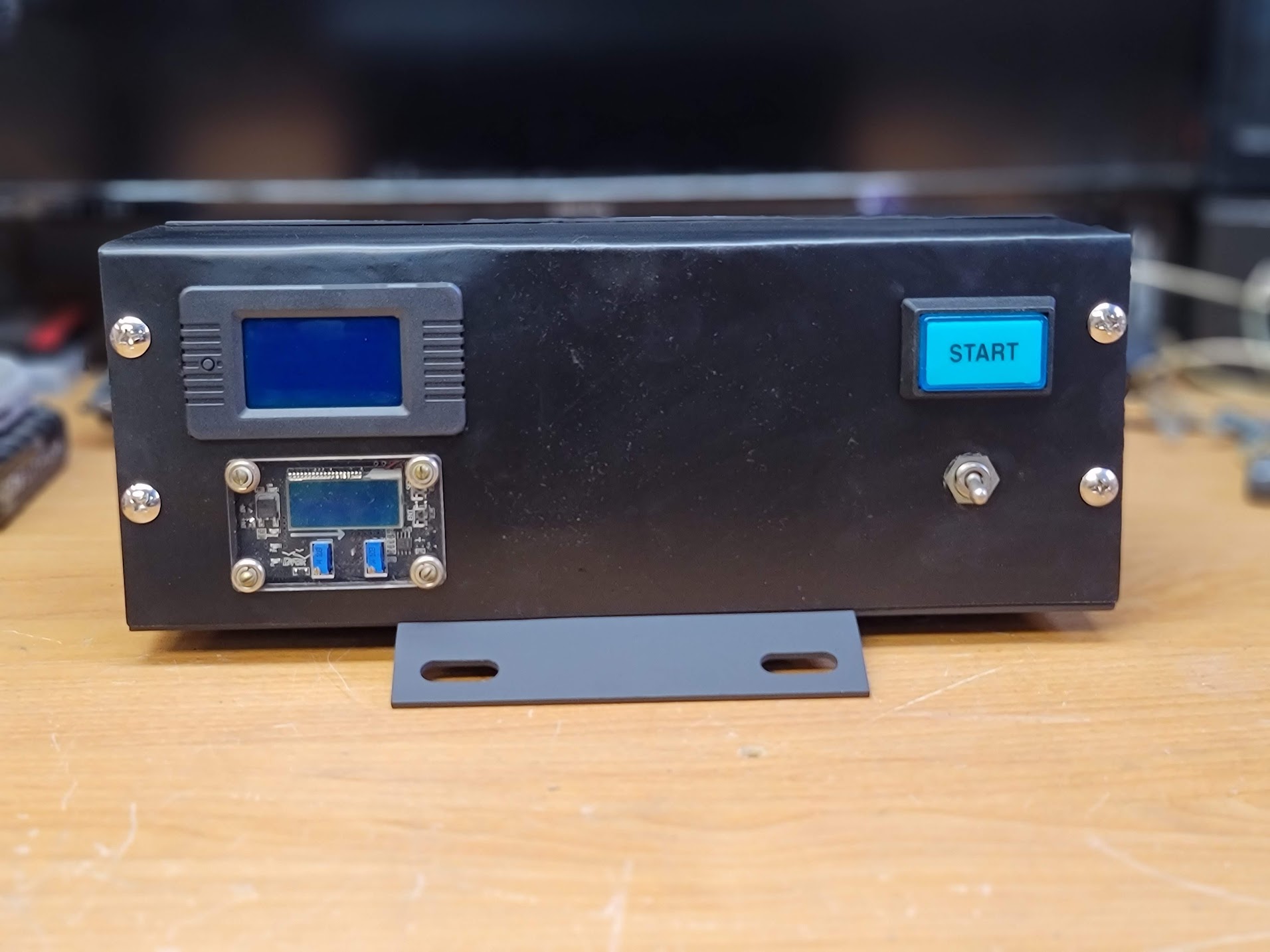
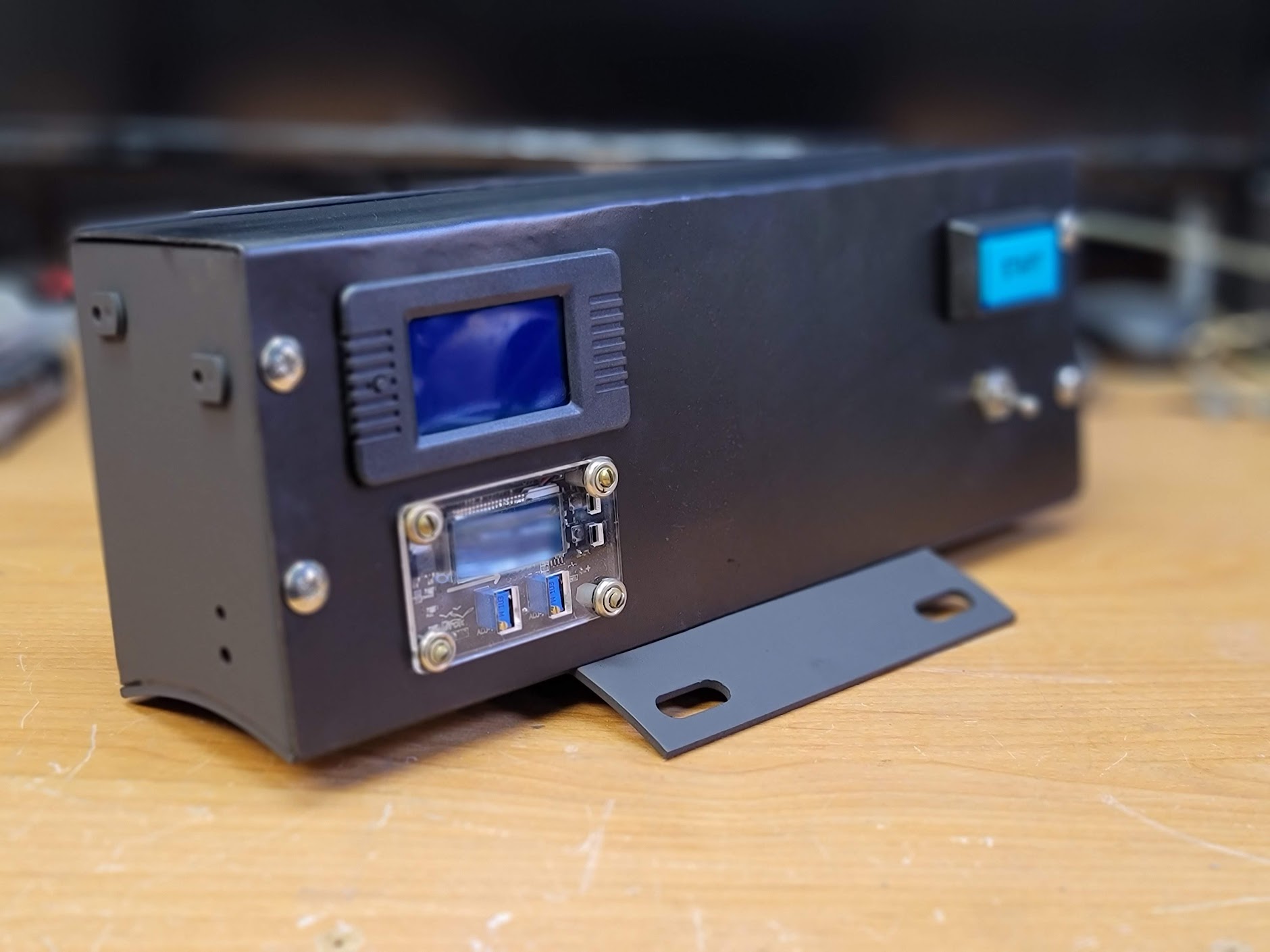
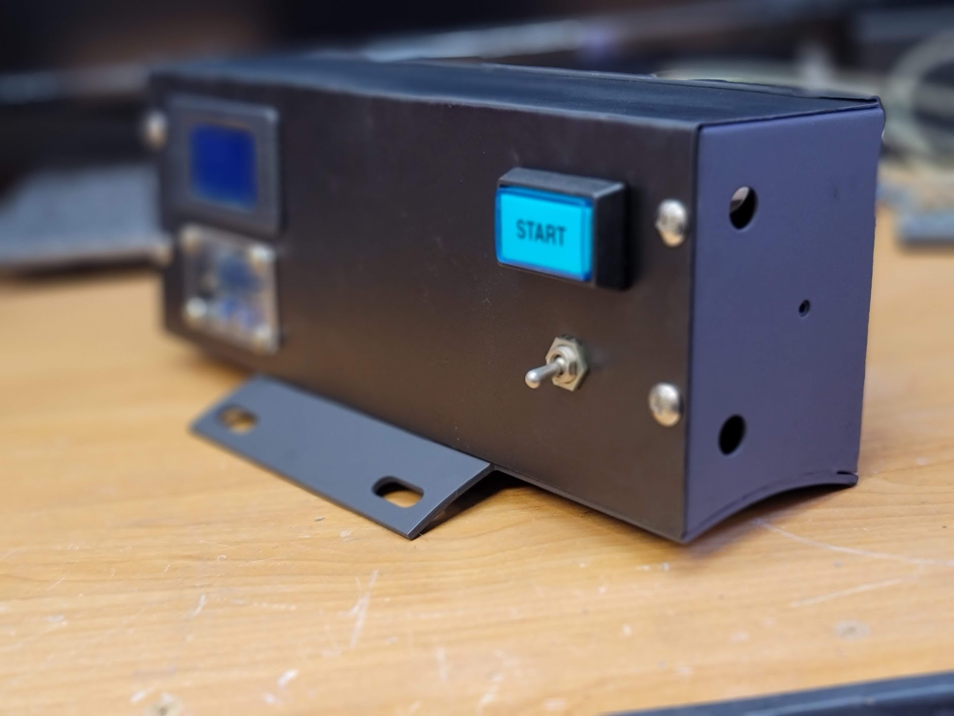
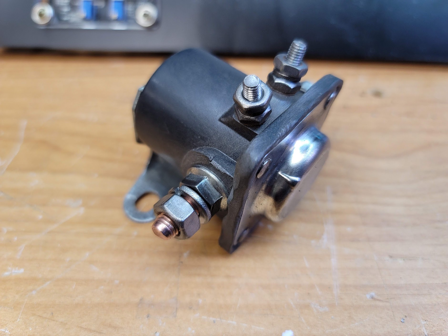
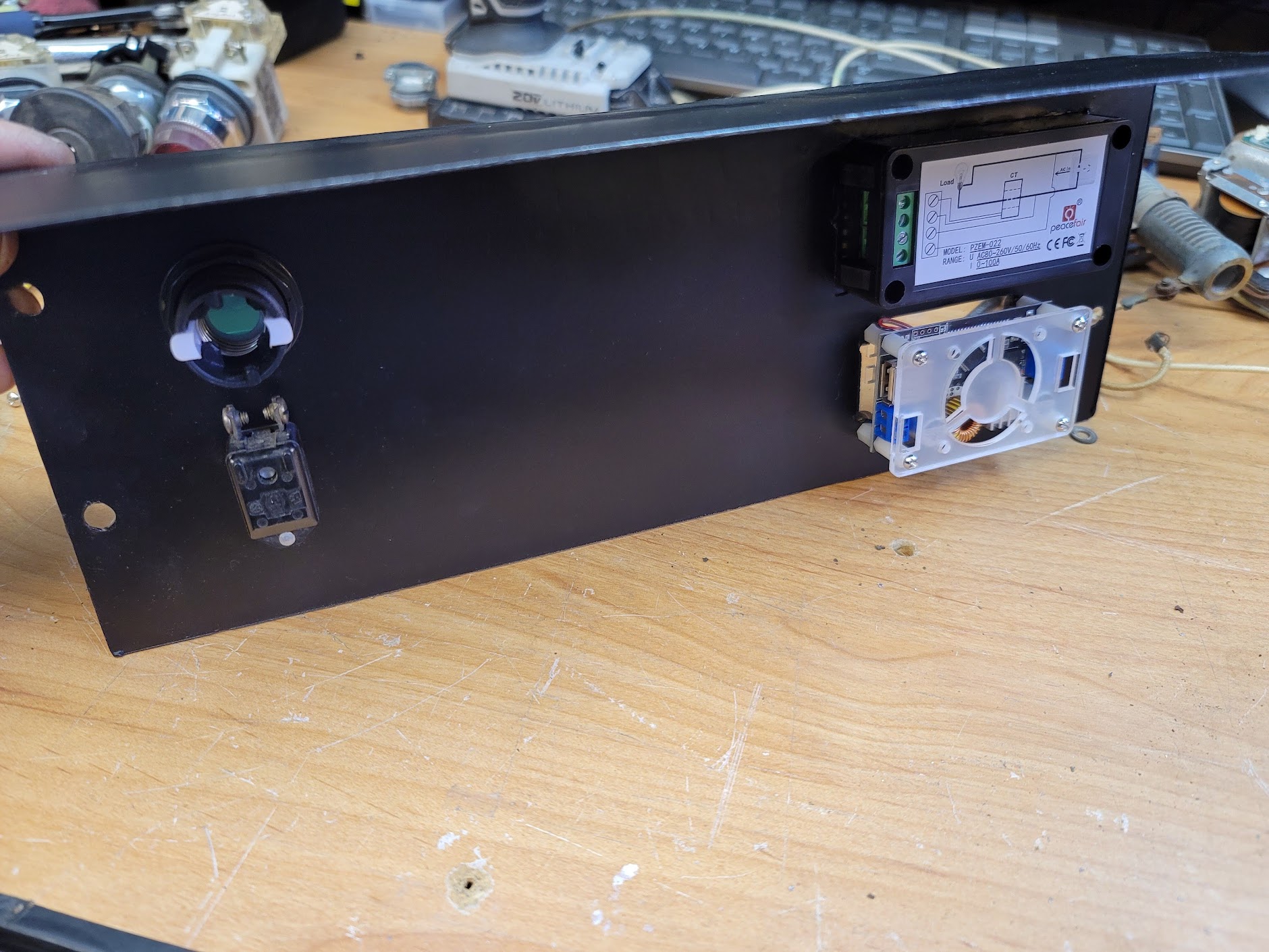
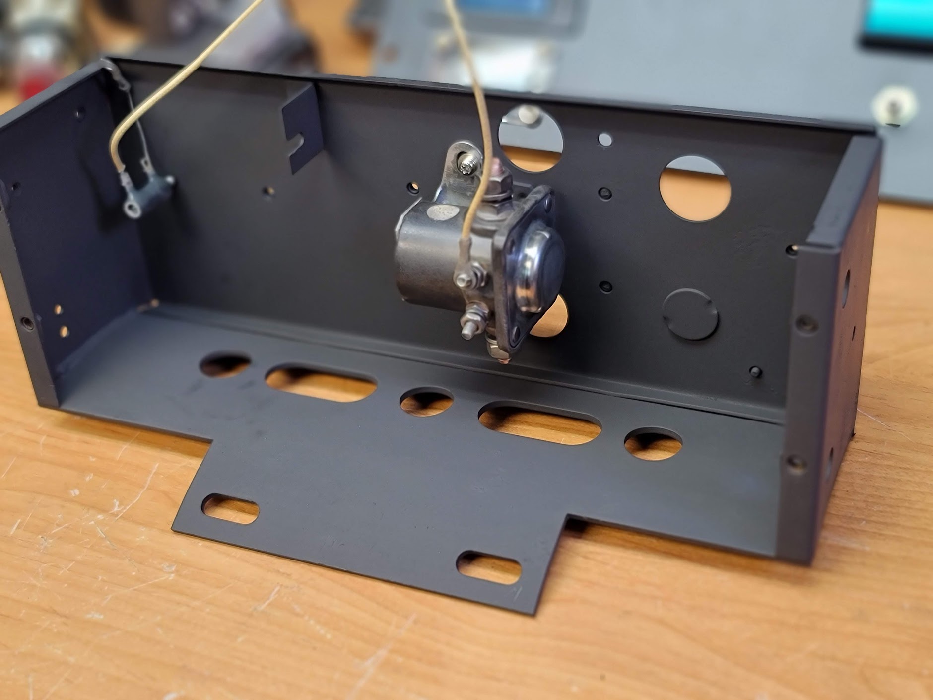
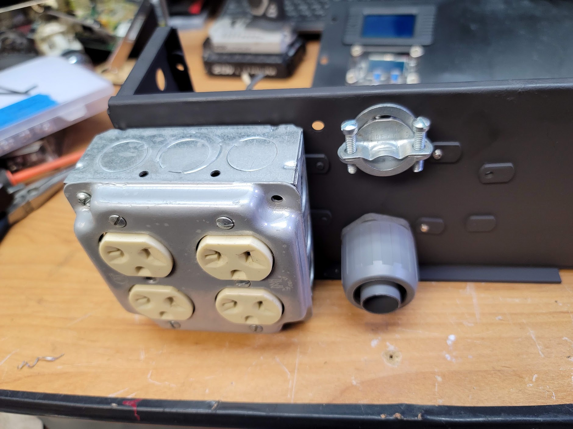
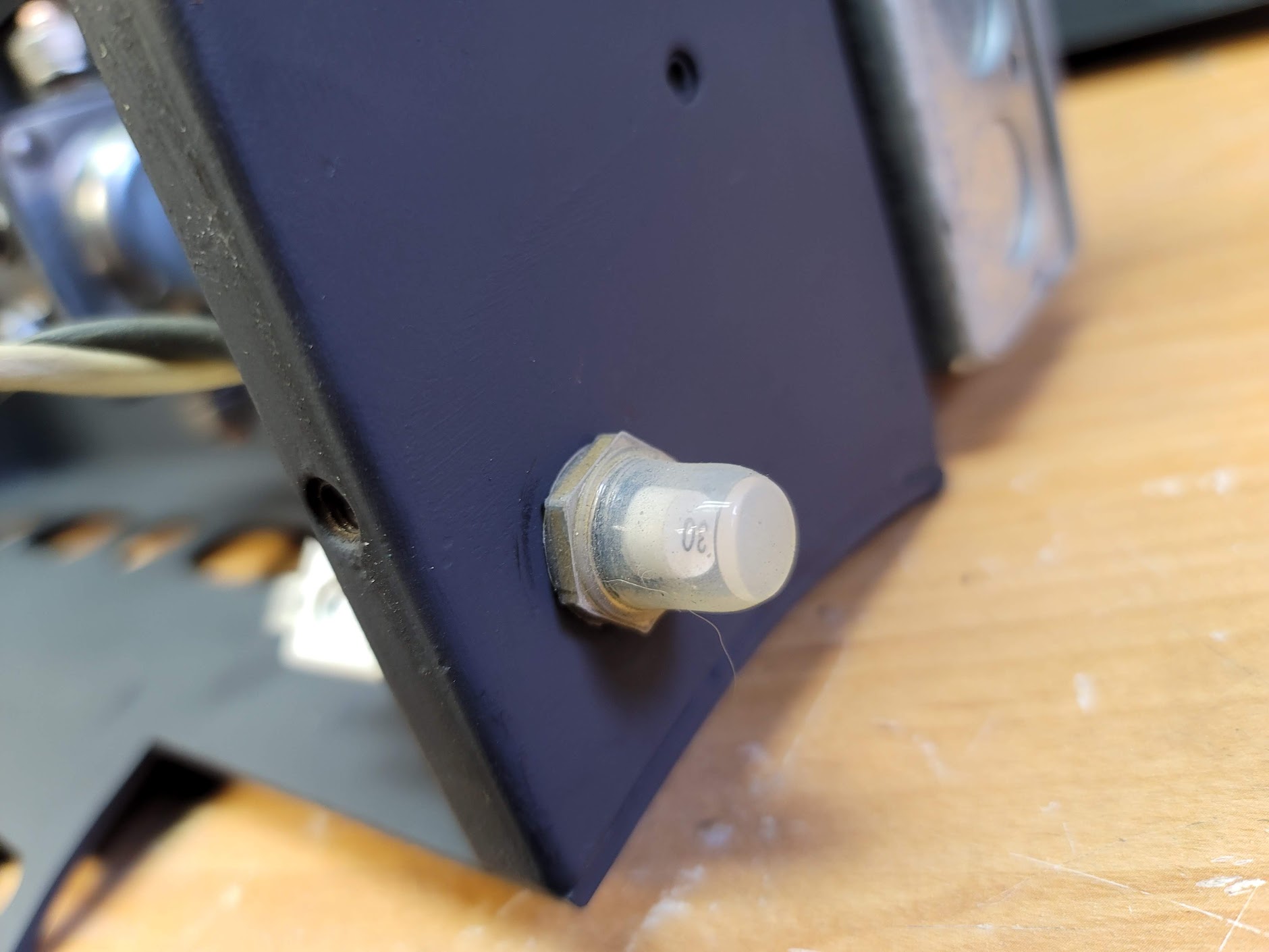
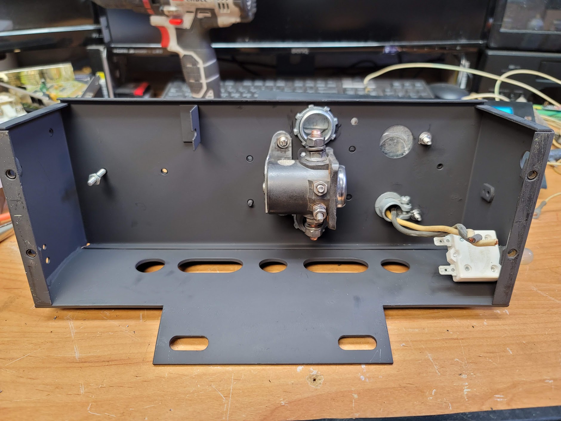
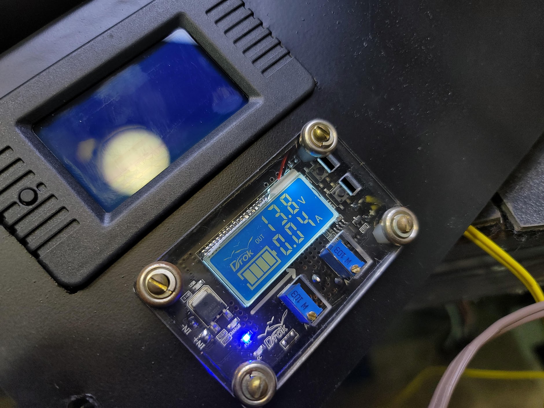
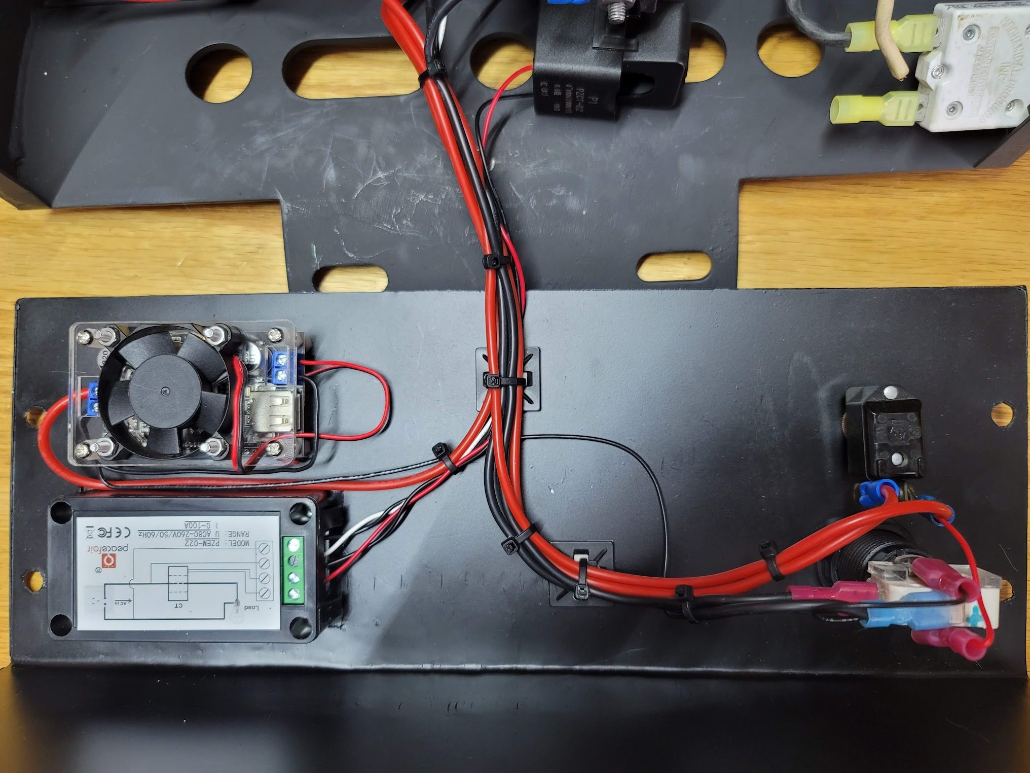
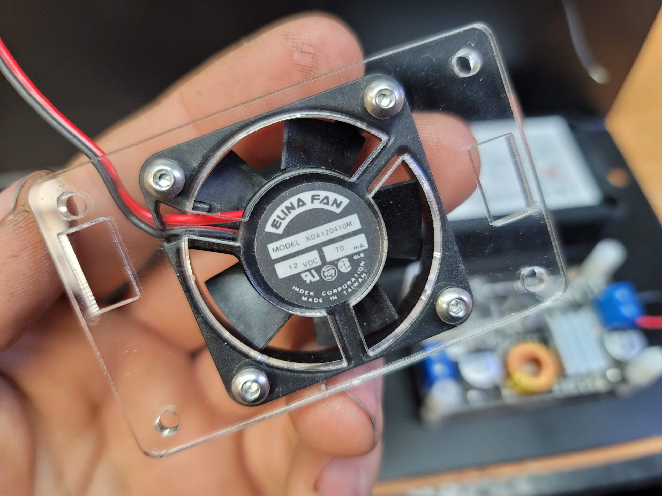
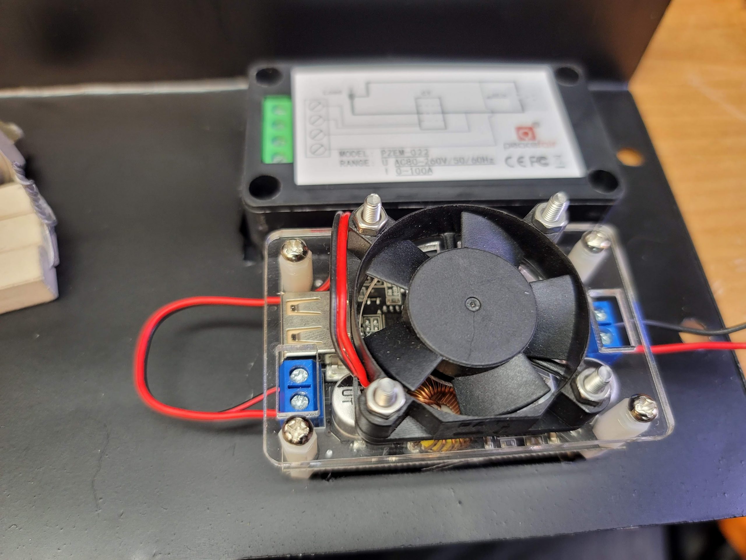
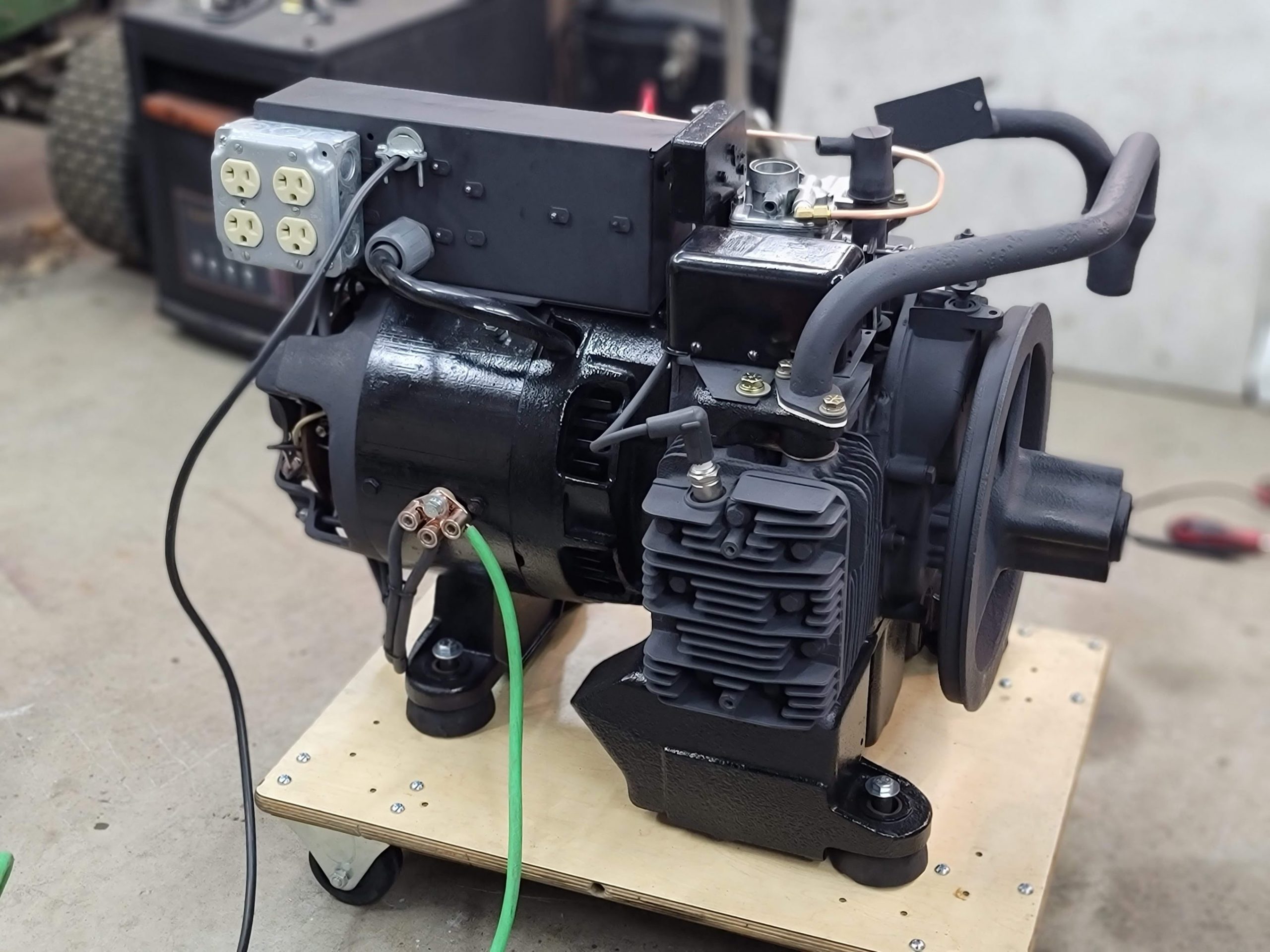
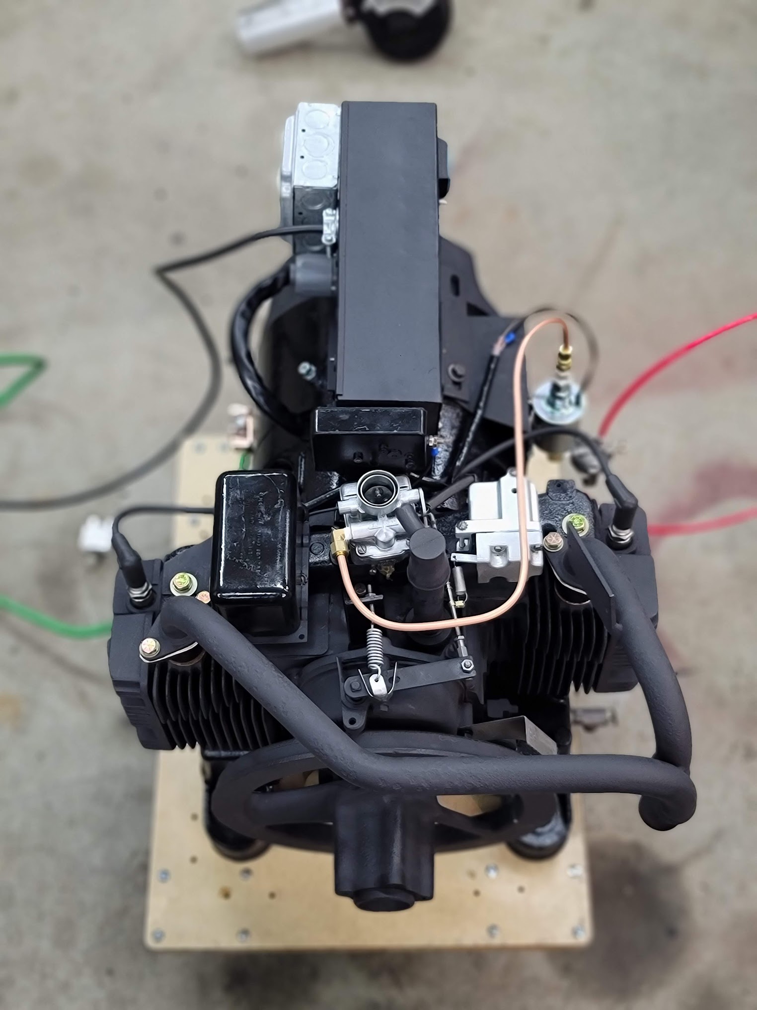
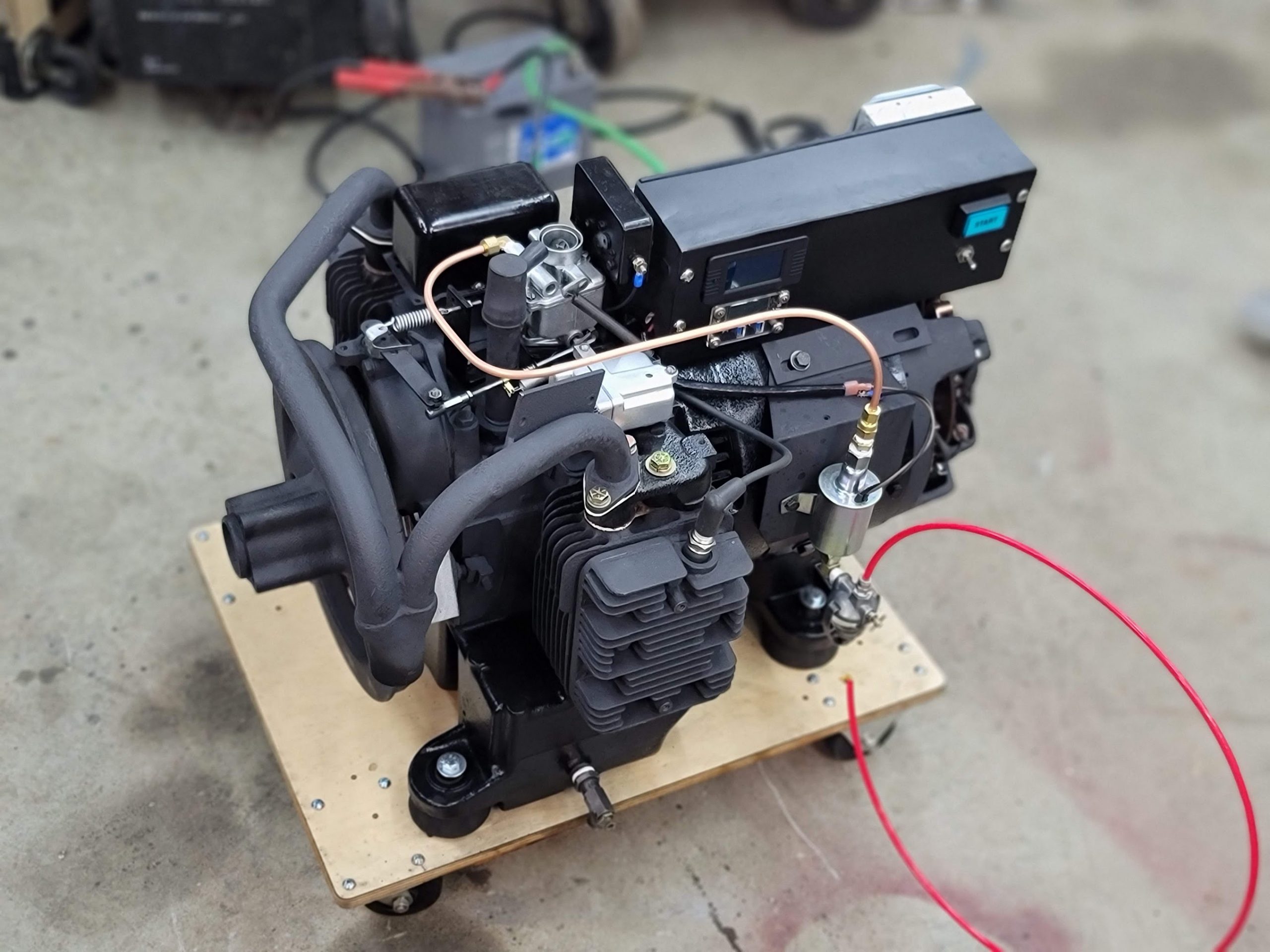
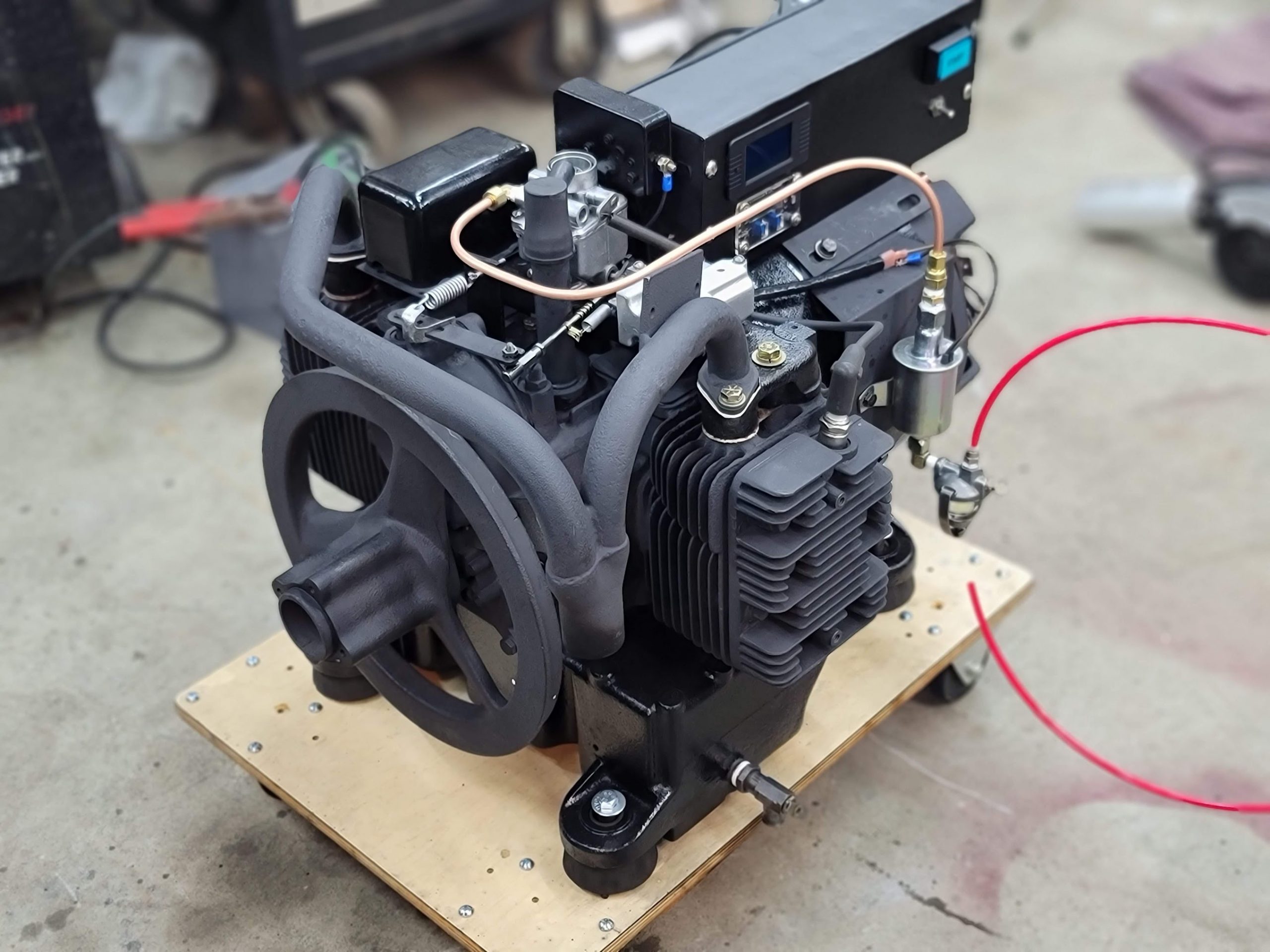
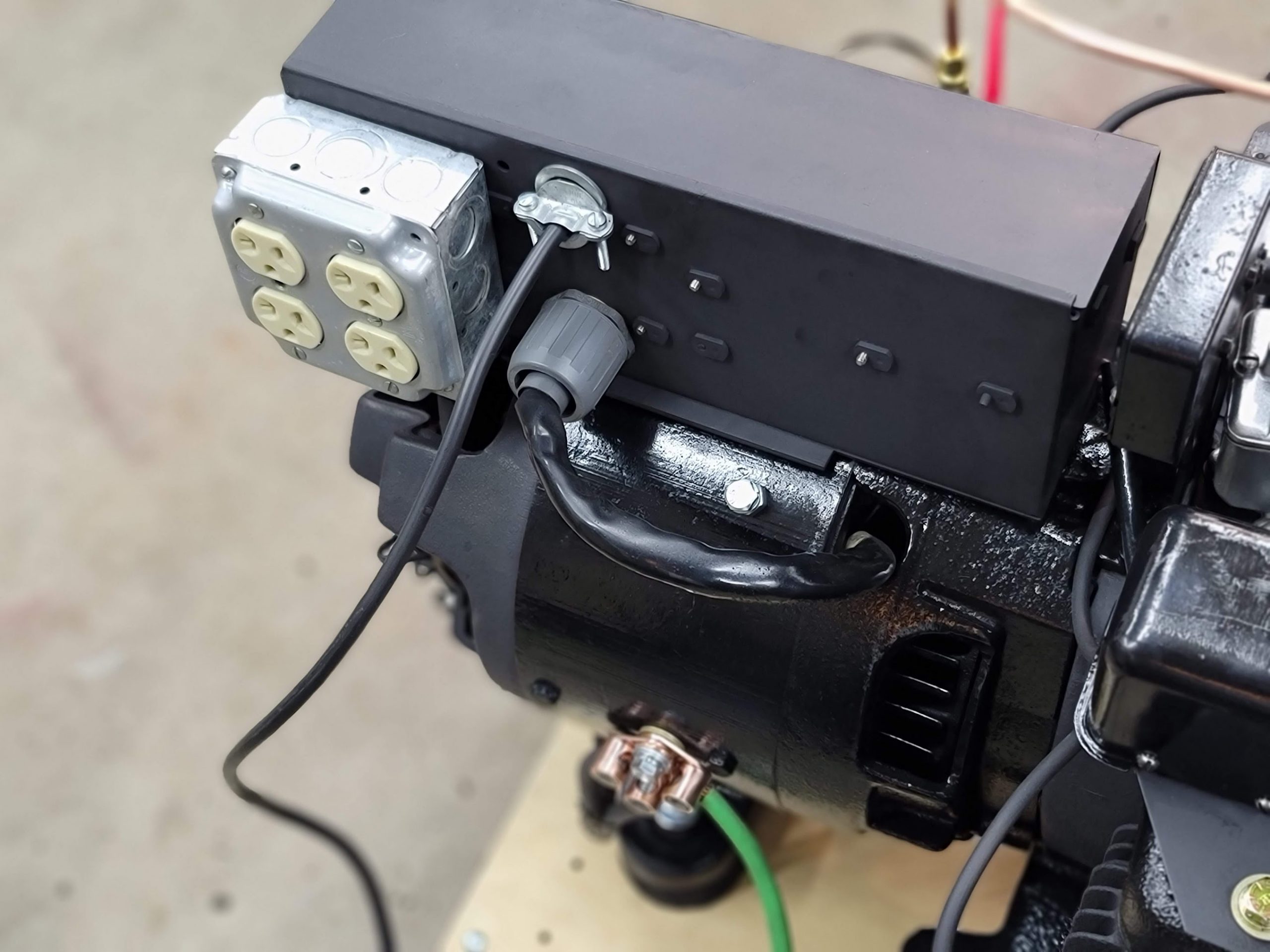
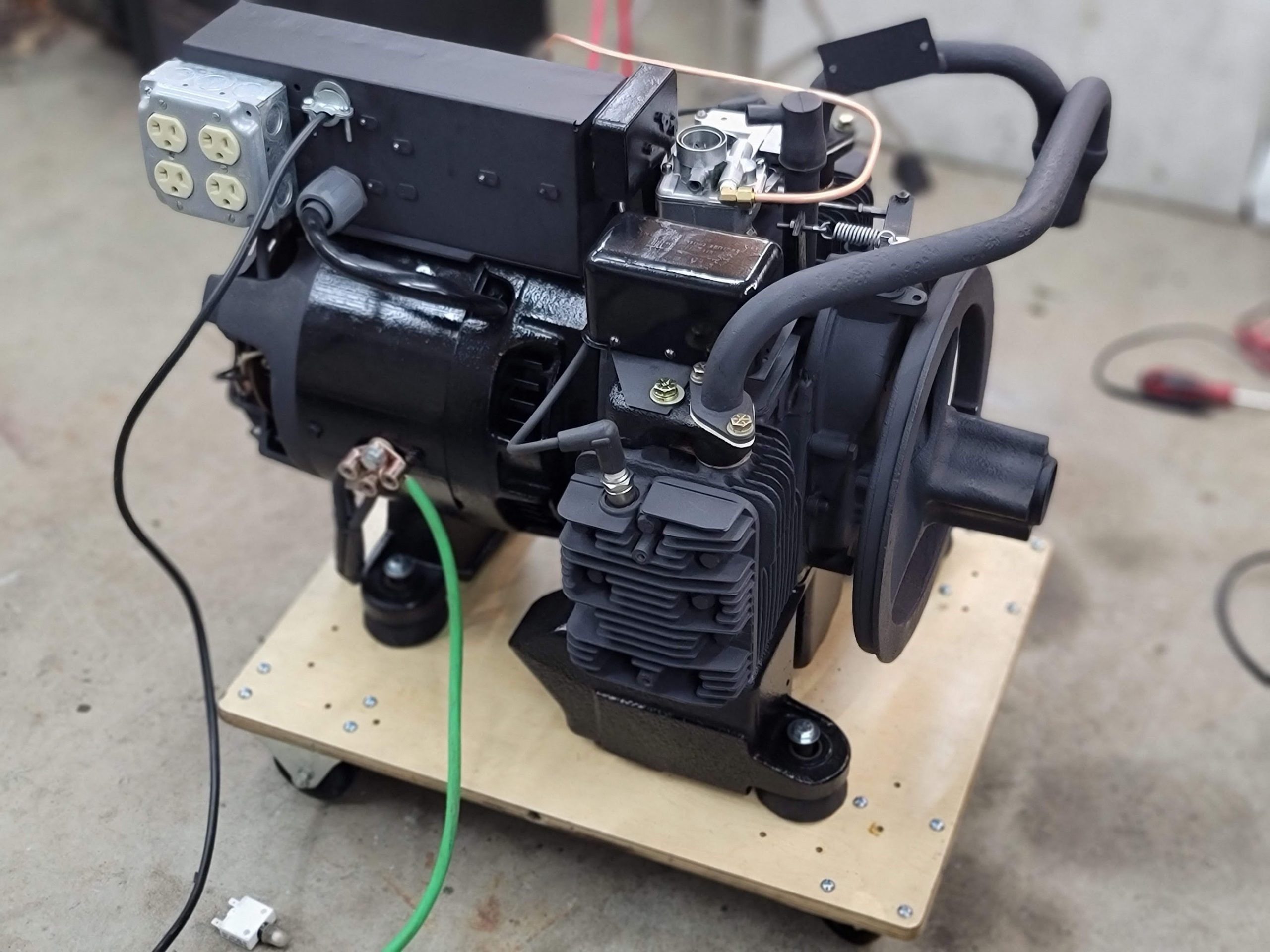
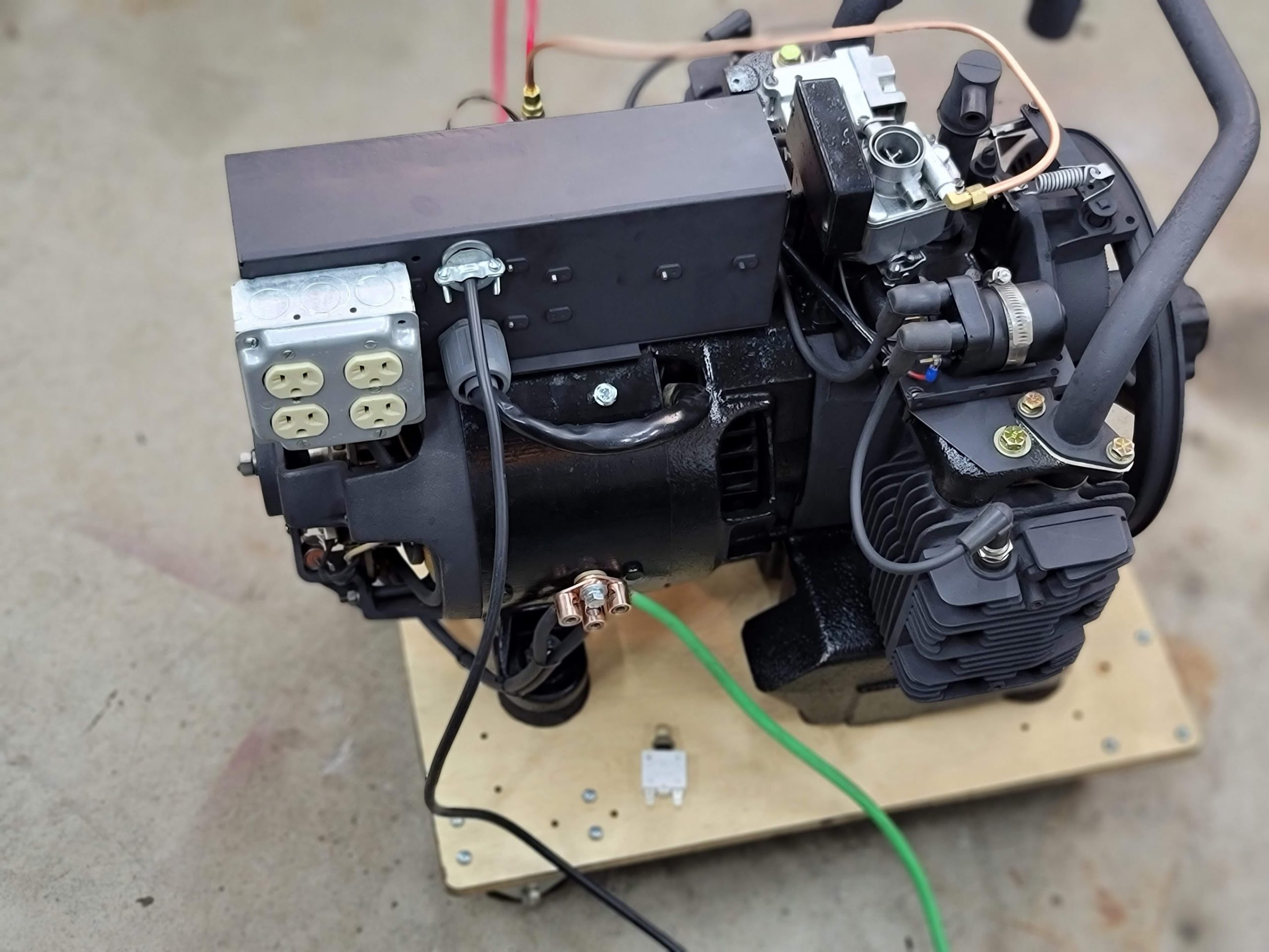
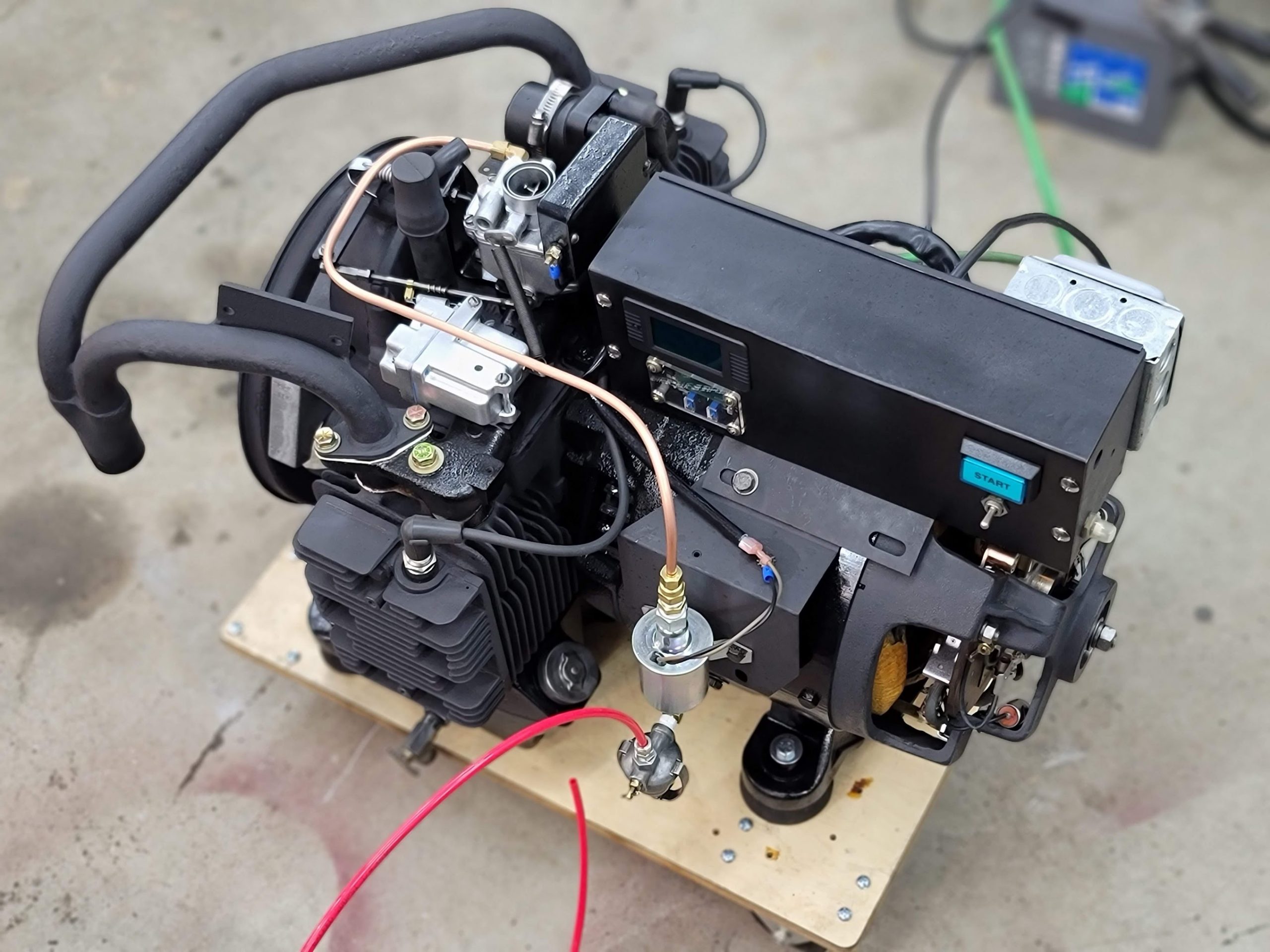
Box mounted and all wired up, now time for a load test! Here I test a 1,500 watt load.
Cycles and voltage are still a bit low, but it handles the load and adjusts well, so I am happy!
Last step is the outside tins!
UPDATE: 2/8/2022 Started work on the tins and hoses
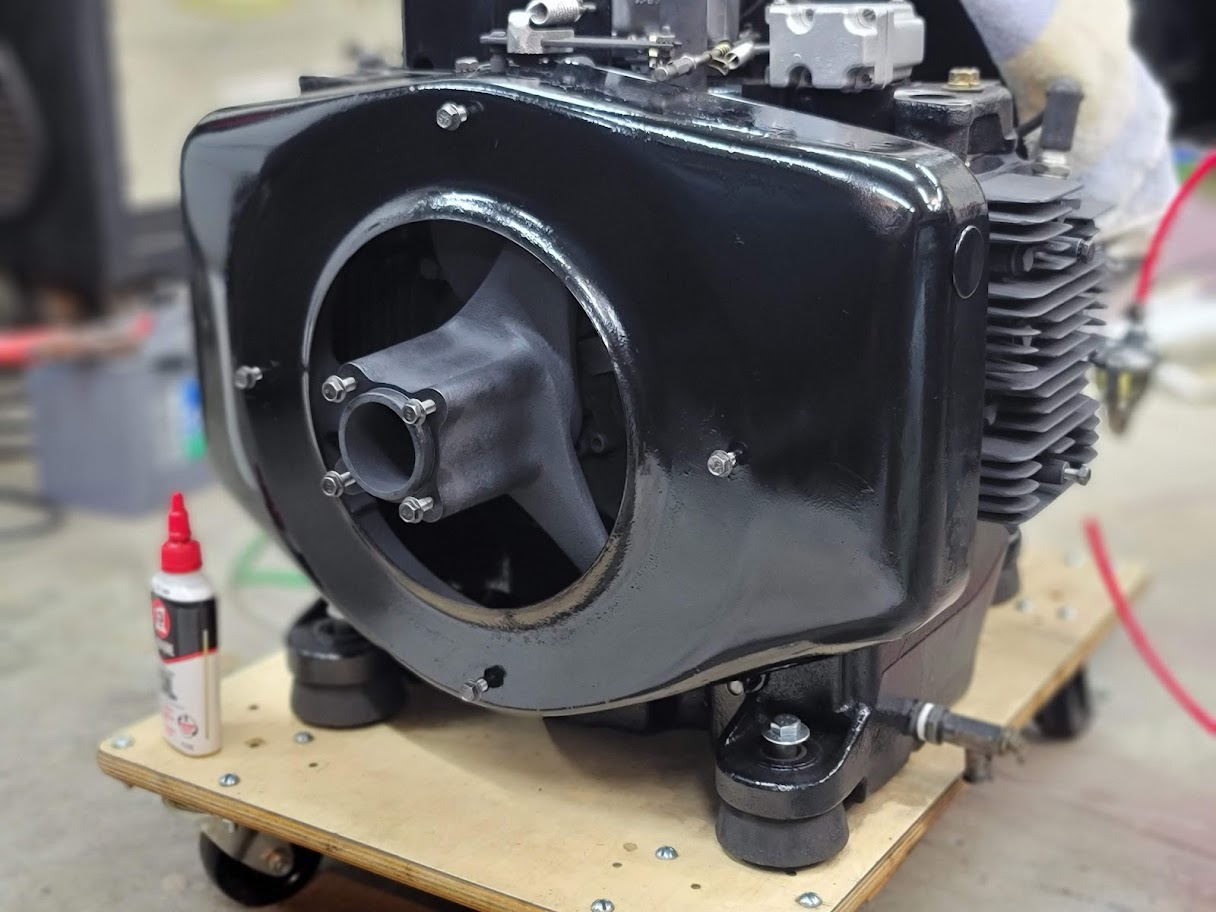
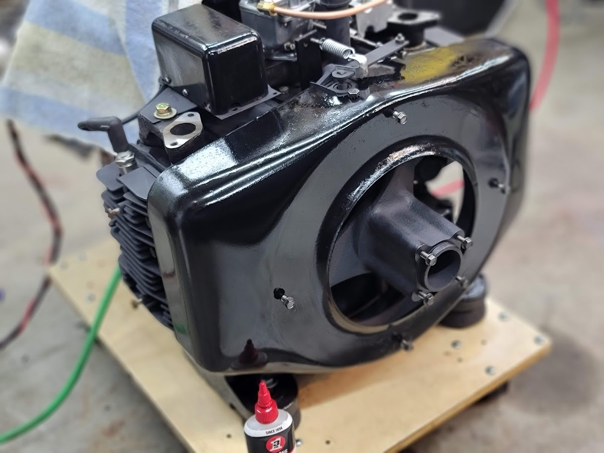
Spent an entire evening cleaning up all the rust on the front sheetmetal. Only have 3 more parts to go!
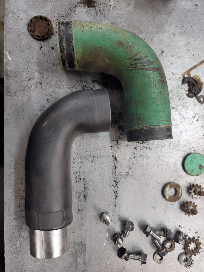
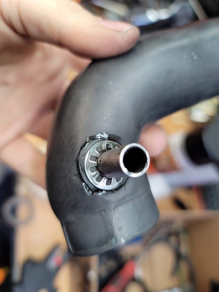
Next step was cleaning up the intake tubes, these took a ton of hand work to get all the old paint and crud off. I had to glue the vent tube interface back on sadly, it did not survive the process.
UPDATE: 2/8/2022 Part 2. Made major progress on the cooling tins.
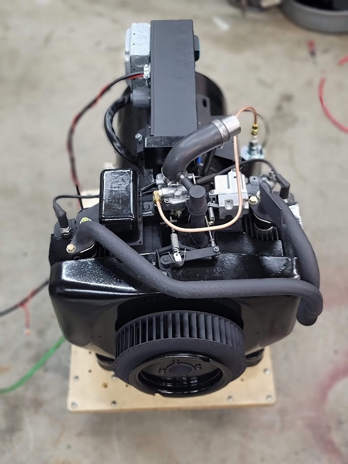
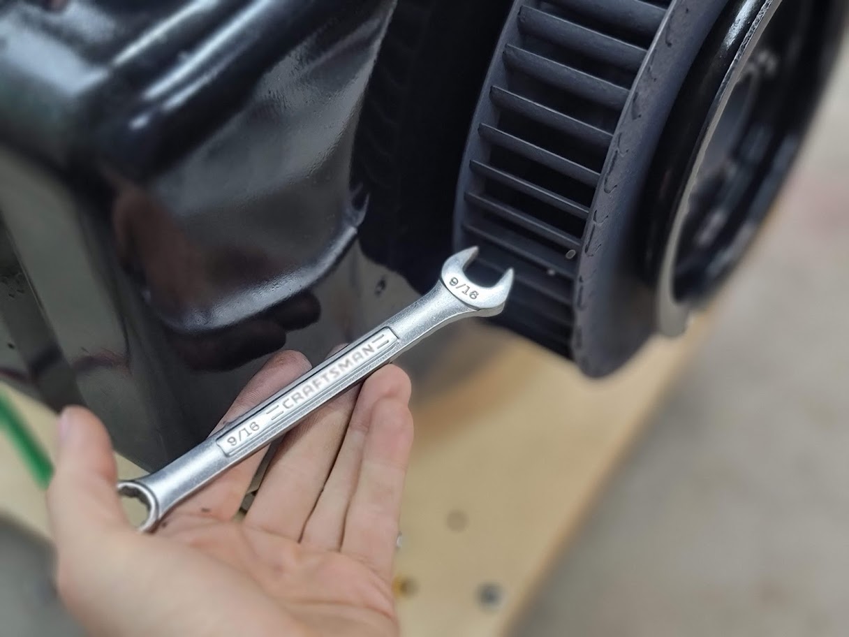
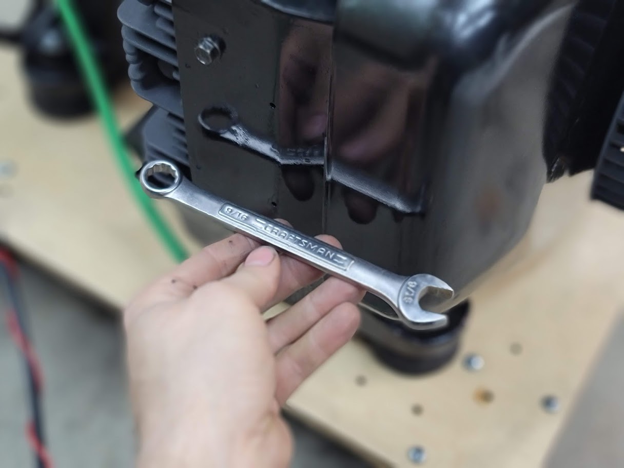
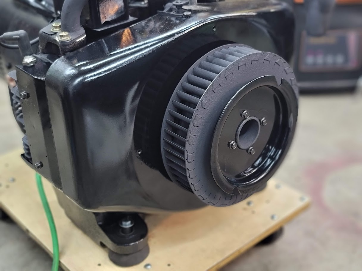
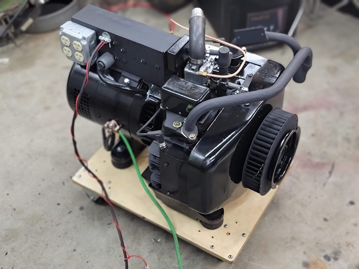
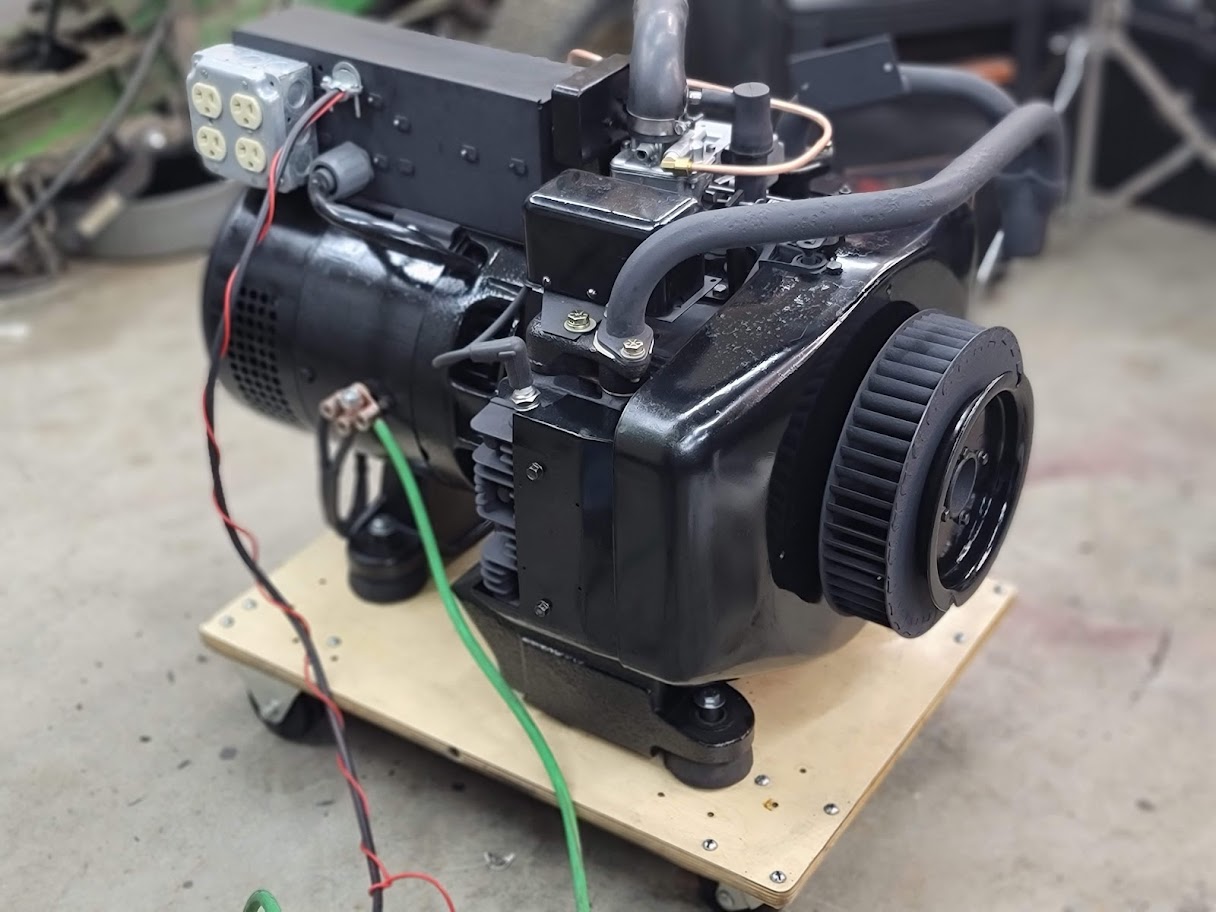
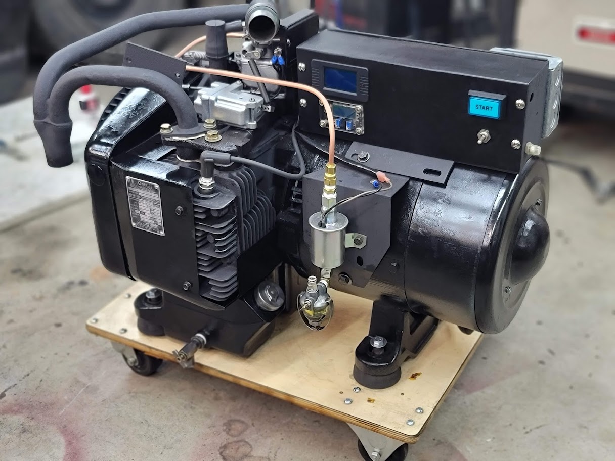
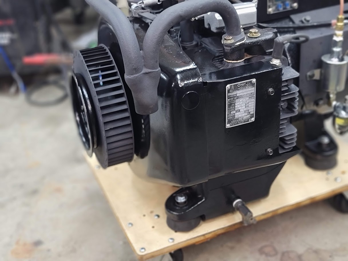
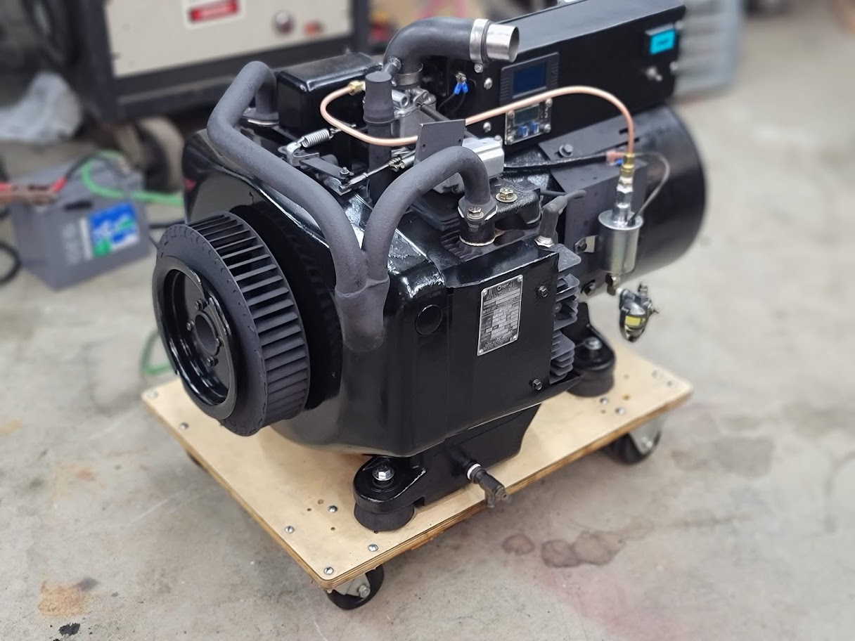
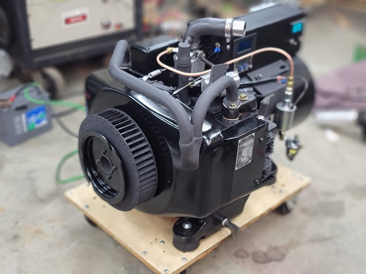
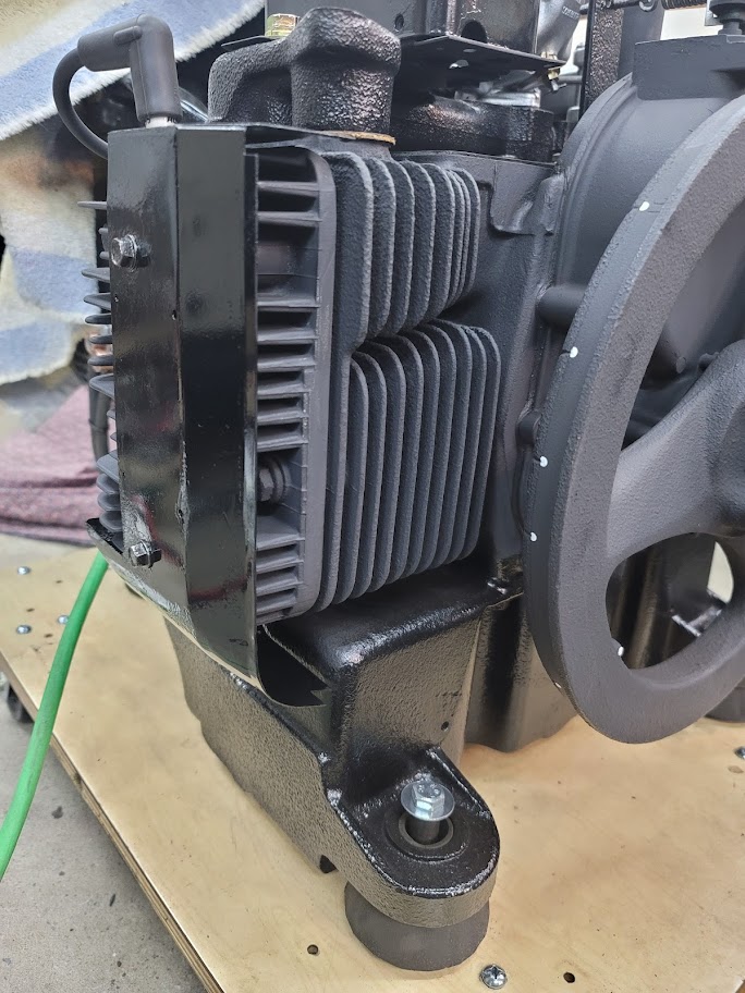
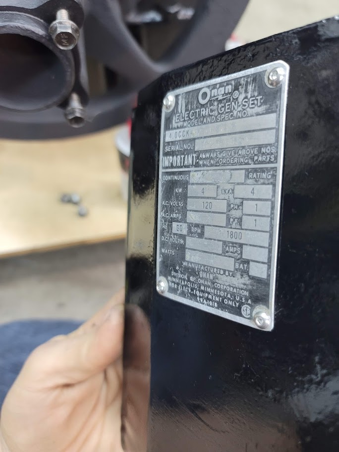
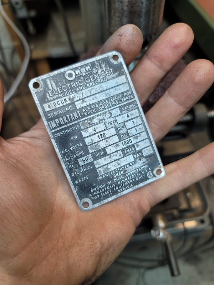
Did the best I could with the nameplate, but it was pretty far gone. Bolted it back on with some stainless Allen cap screws.
I was now able to run it long enough to adjust the settings, it runs so smooth now.
Last step is the front air duct that goes around the fan, and to figure out the mufler!
Oh and the air filter is on order, I think it will look neat. Stay tuned!
UPDATE: 2/10/2022 Power went out today at the lab… more on that soon.
Last night I spend a ton of time cleaning the old front shroud.
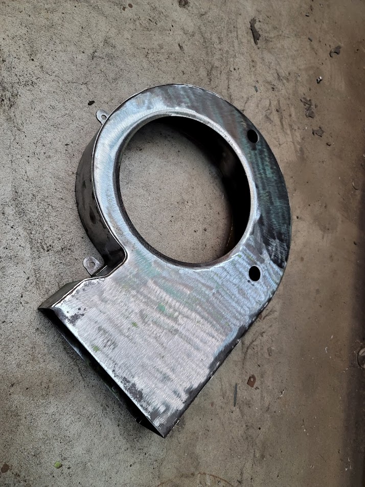
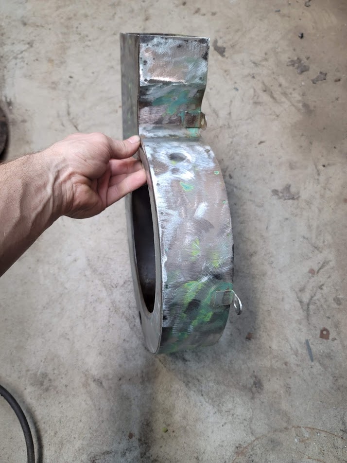
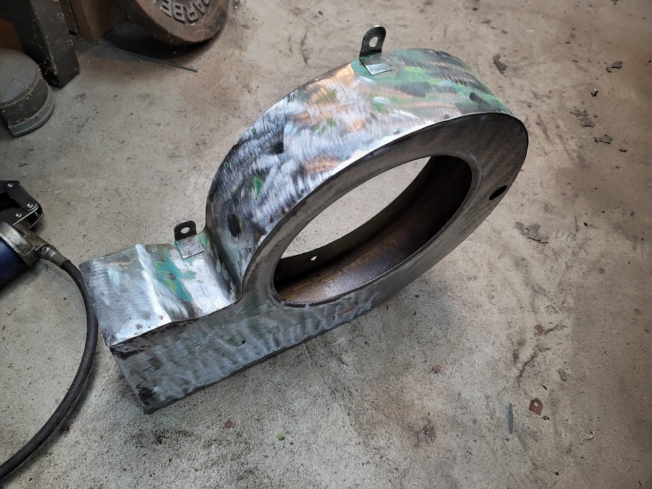
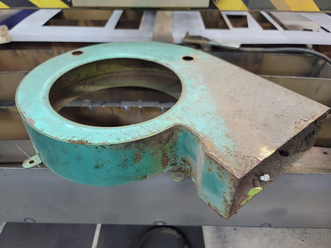
What a complex shape to wire wheel and sand, the inside was the hardest part. But was able to get it into paint and mounted!
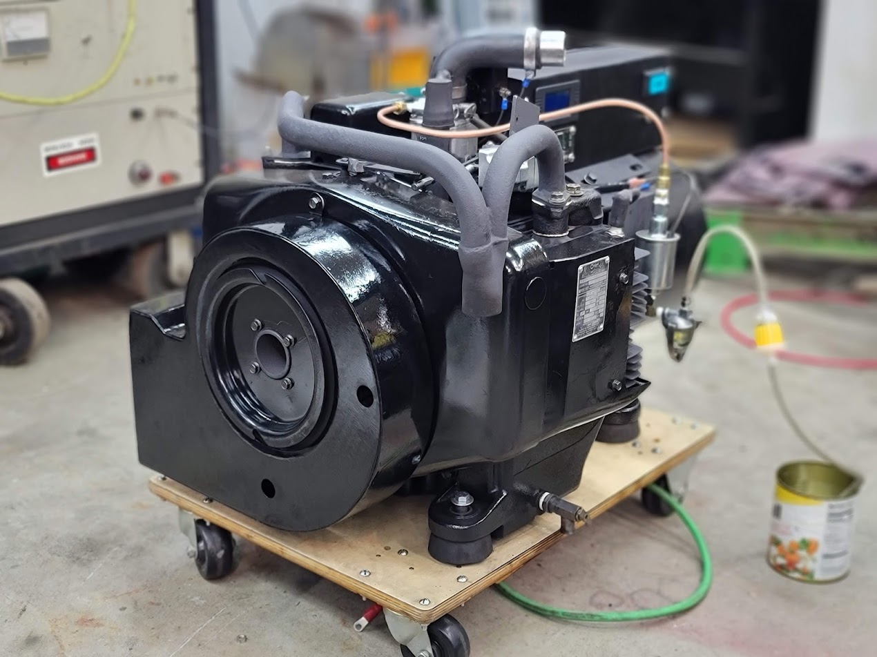
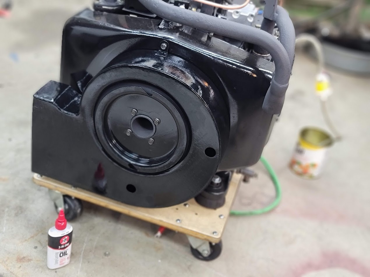
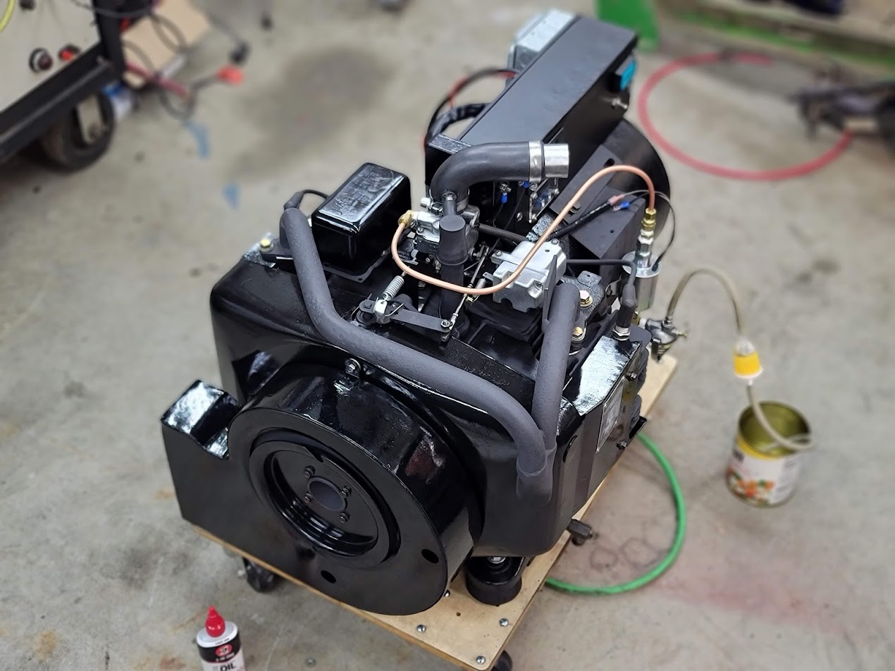
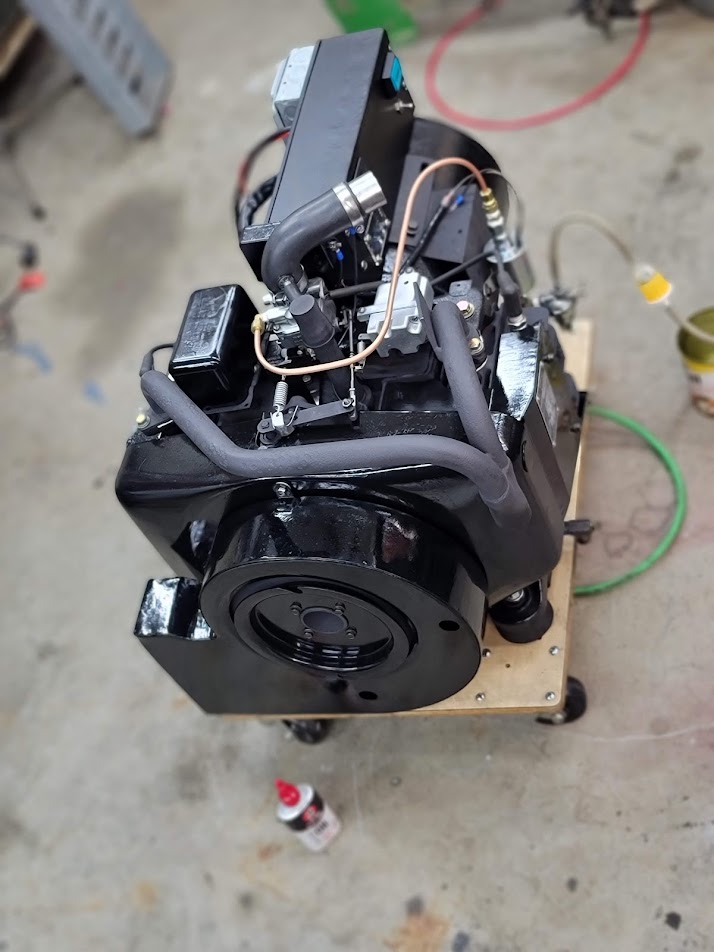
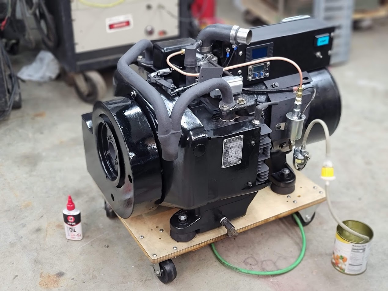
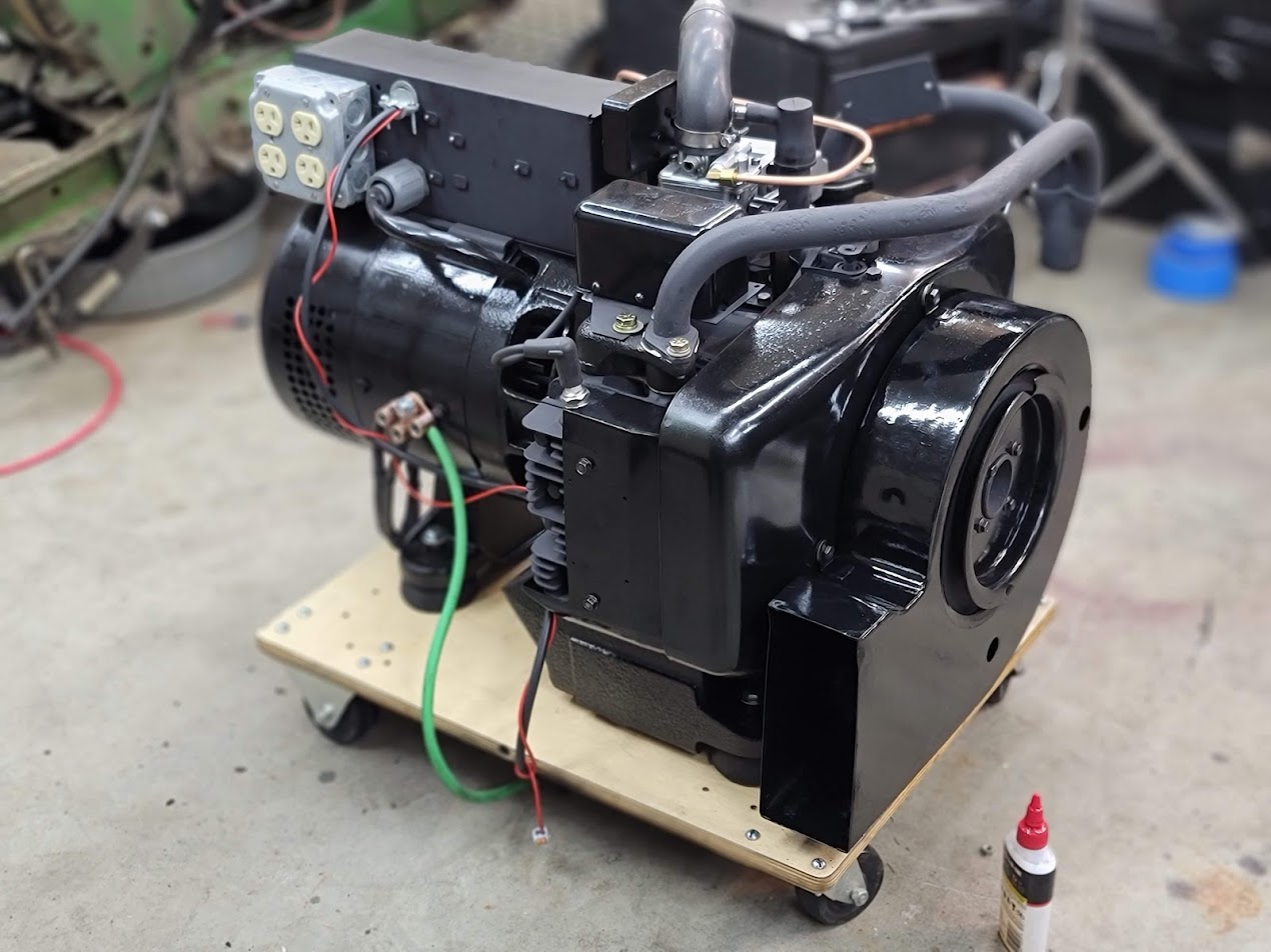
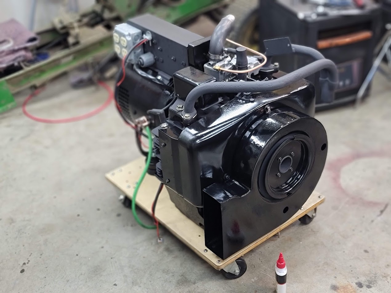
Wow does it look complete now! … Here is where things get interesting…
This morning while working in the lab the power went out! … here is the problem, the battery bank conveniently was finished last night but was not close to the generator at all!
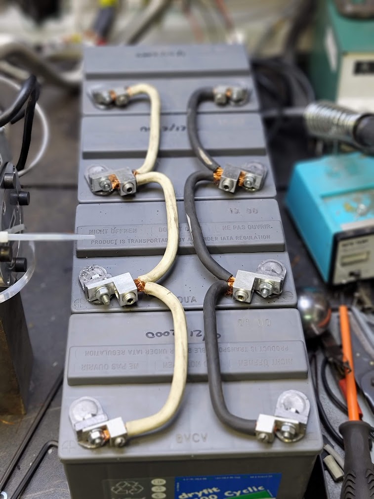
Here it is sitting on the main bench, so with the power out, I had to remove all the wires move each battery one by one to the shop and wire it up in the dark.
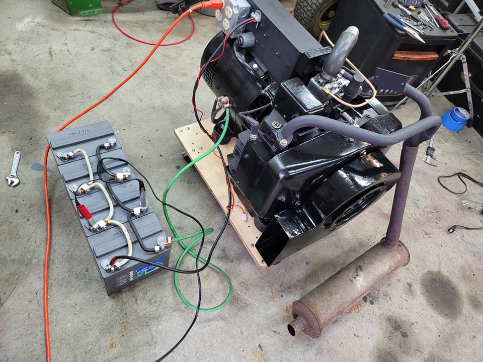
After the power came back I grabbed this photo, I had to jam the muffler in place for under full load it makes some noise wow! The governor was not set perfectly so the UPS was not the most happy with me, but it did work! I will work on getting the governor set perfectly soon! The fan shroud worked perfect and kept everything cool. Had it running for almost an hour. Talk about a crash course test on a rebuild ha!
Last step is Air Filter and muffler. Almost there!
UPDATE: 2/12/2022 Decals!
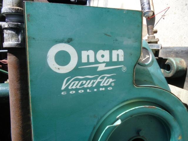

I wanted to recreate the original logo, sadly mine was long gone, so closest I could find was the image above online. I took that and in lightroom adjusted for geometry, perspective, and color, to make the Black and white logo you see above.
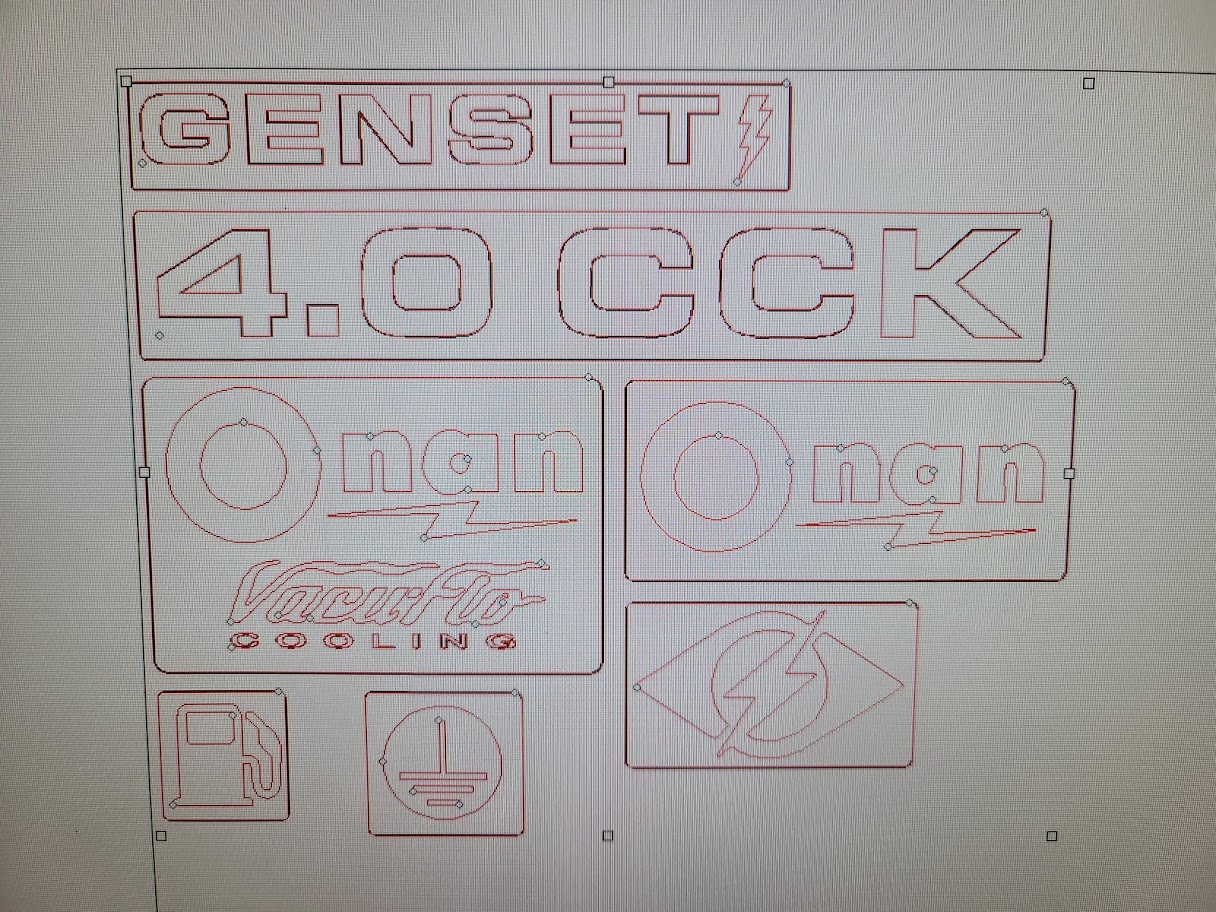
Used that to vectorize the logos and made some new ones.
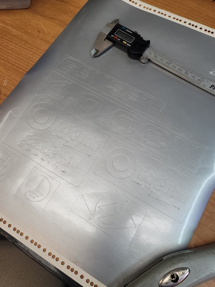
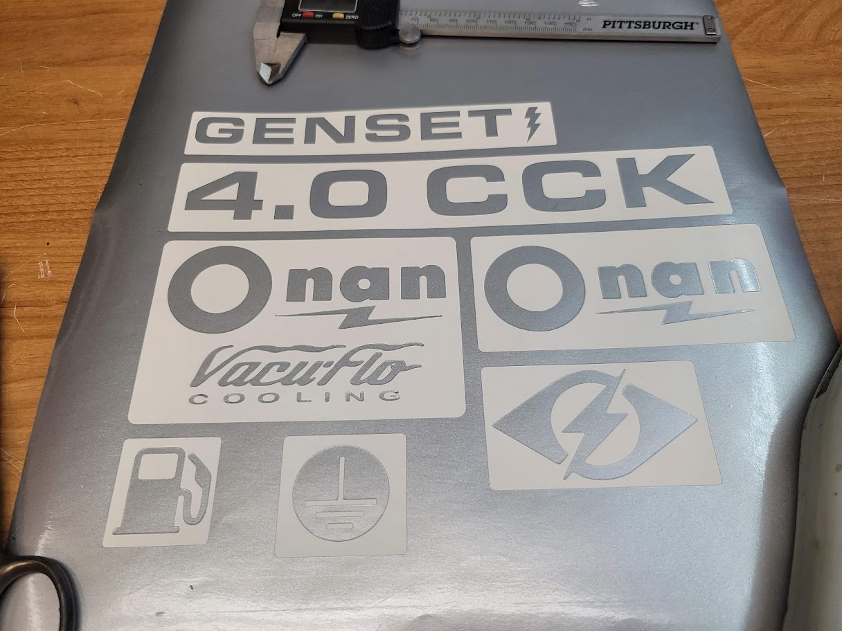
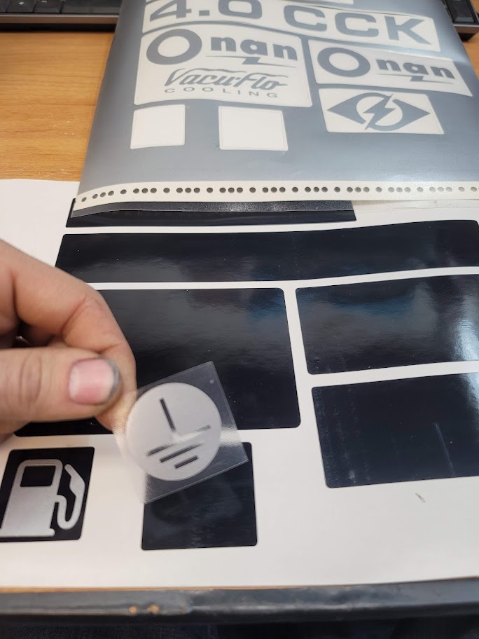
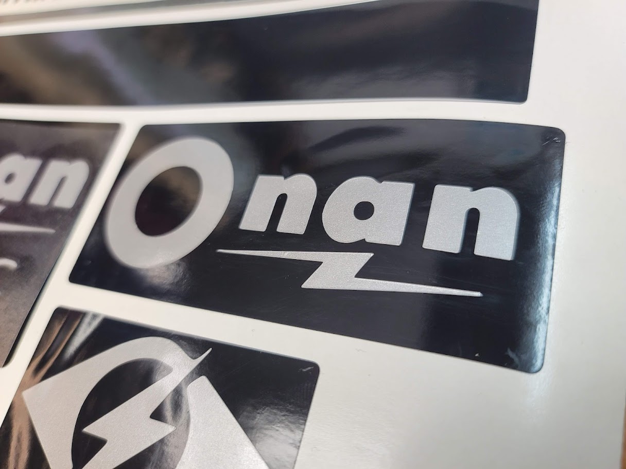
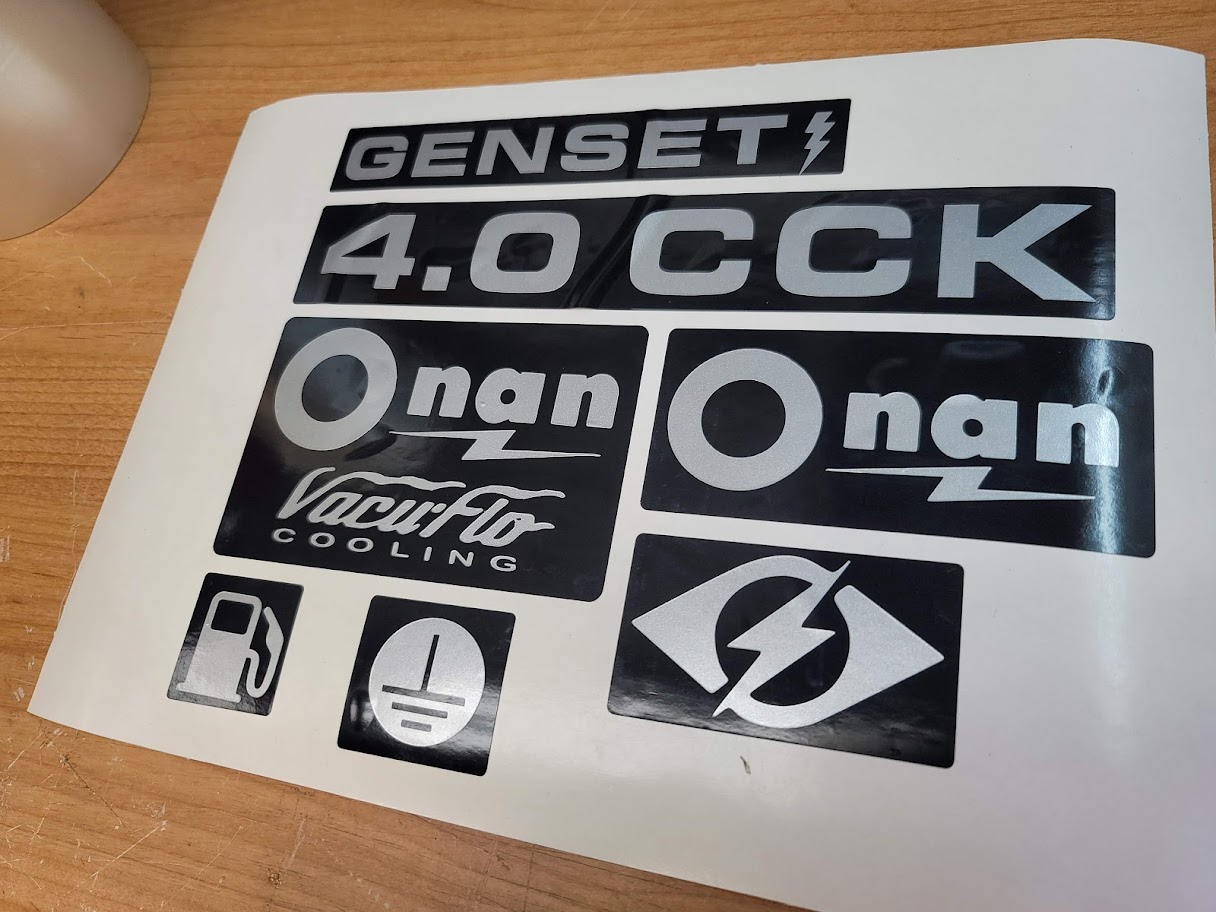
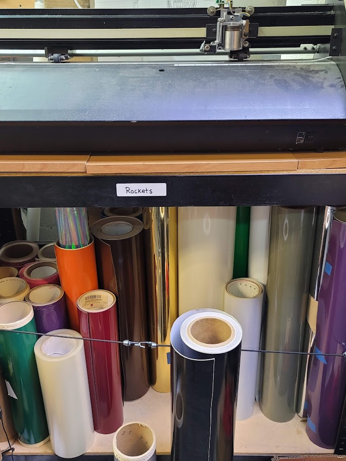
Fired up the modified Vinyl cutting CNC machine to make some decals! I used metallic silver on top of Gloss black to make into a peel and stick decal.
Here is the DIY CNC Vinyl cutter doing its thing, always fun to watch it go, a computer controlled razer blade!
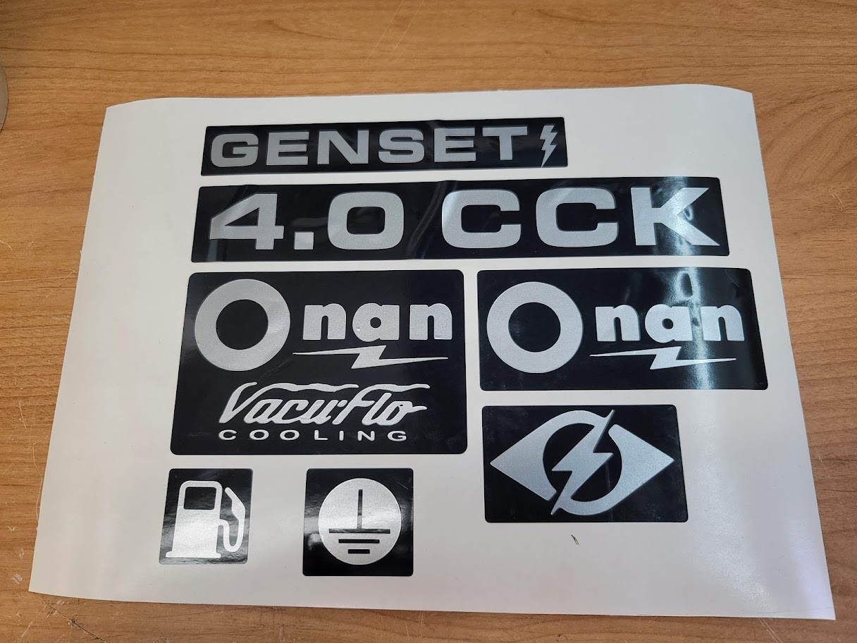
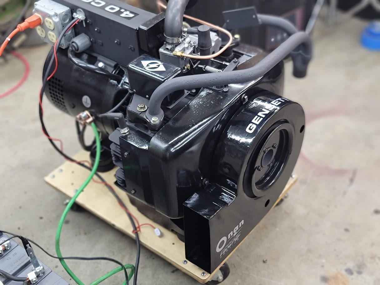
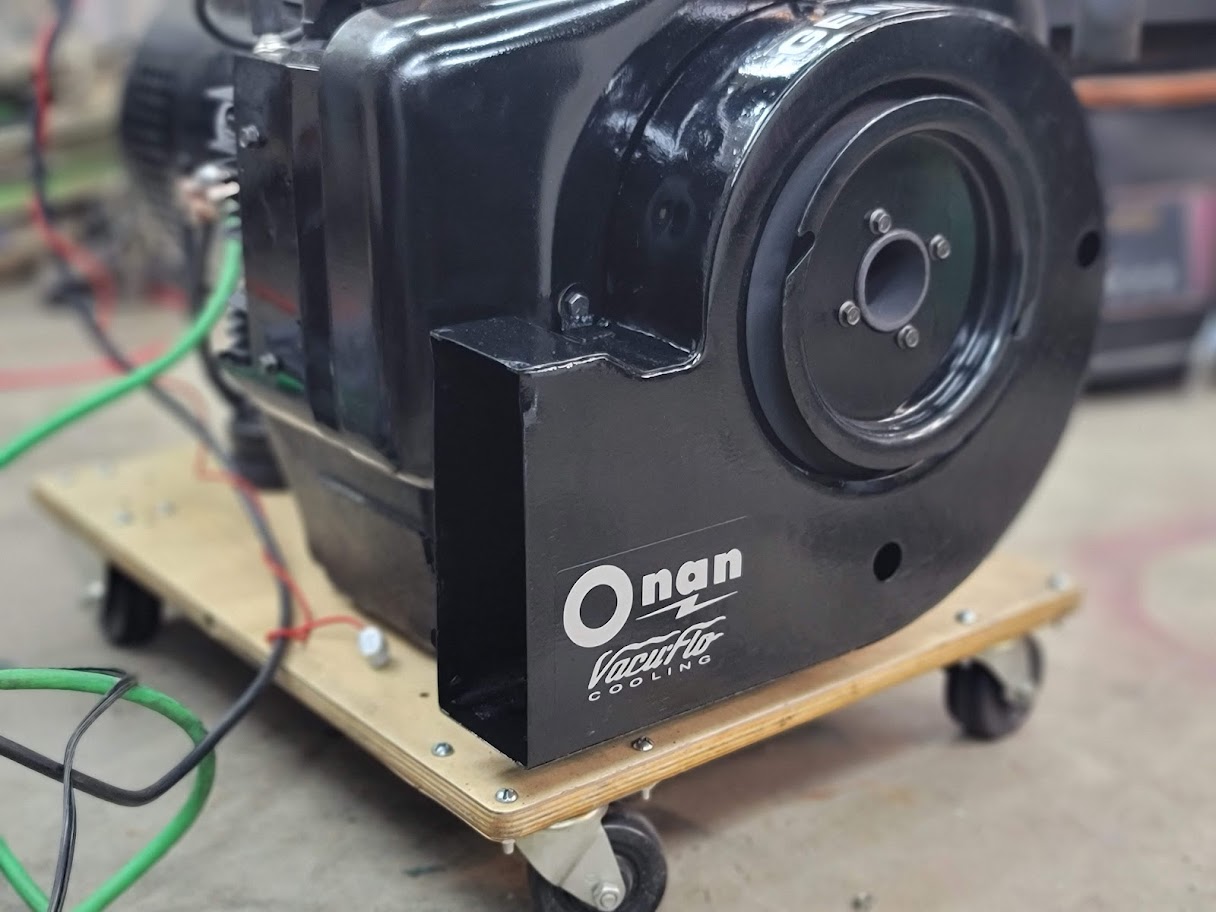
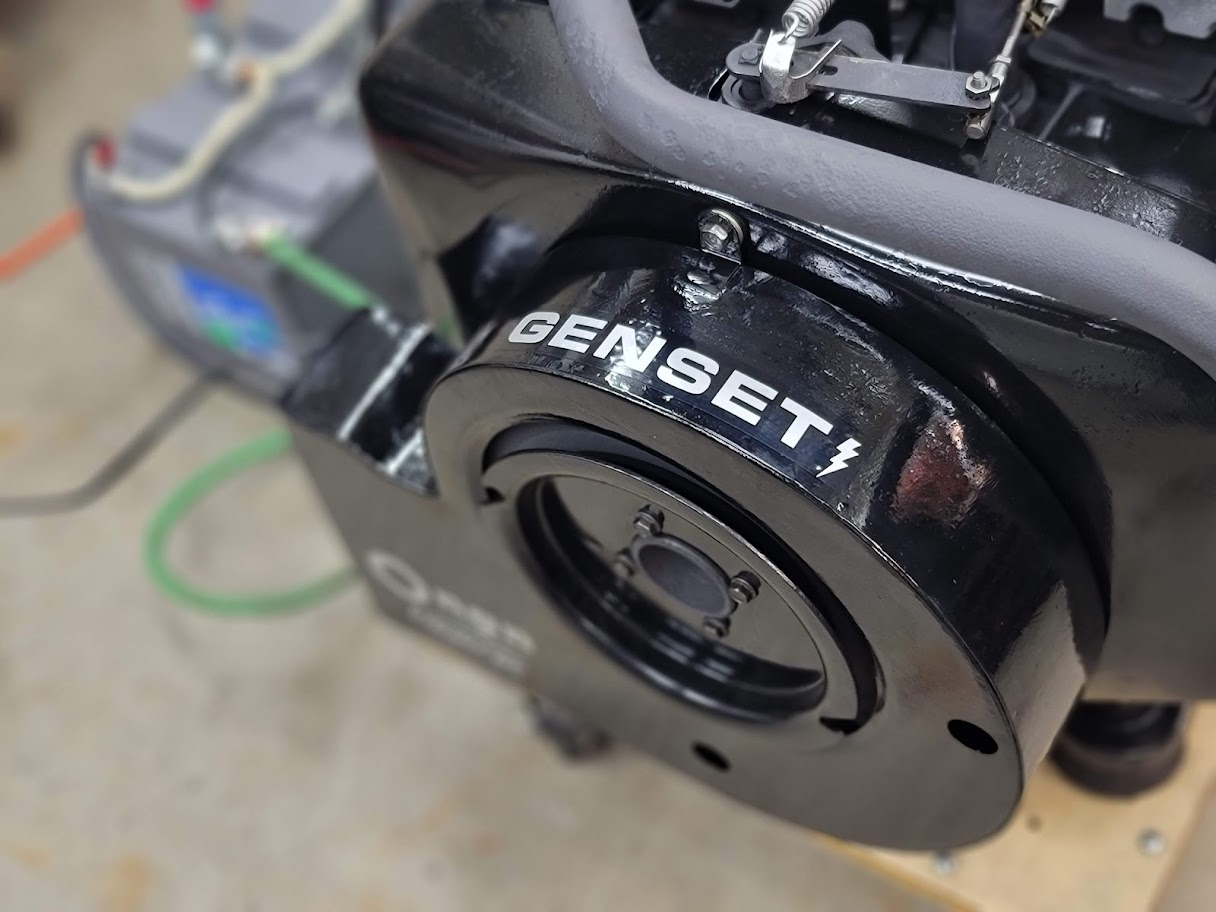
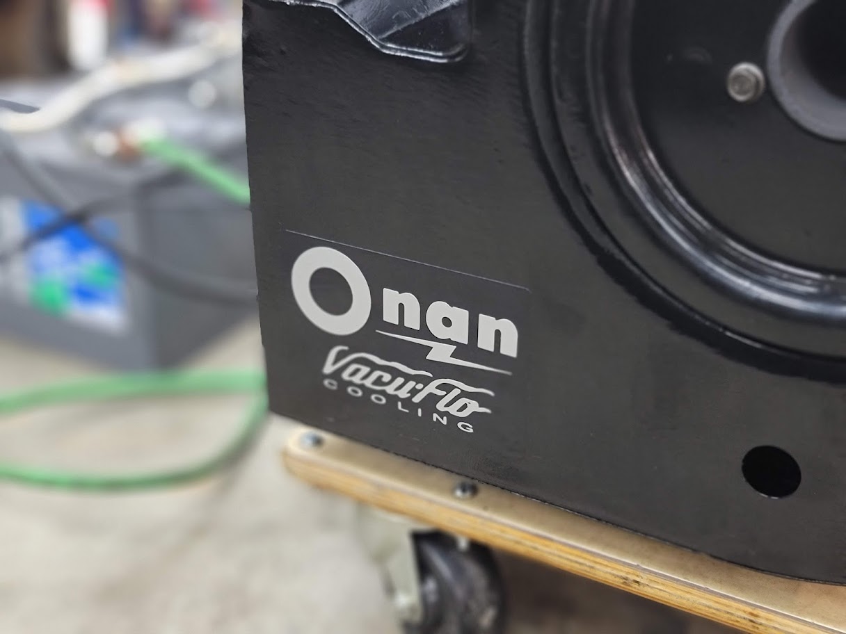
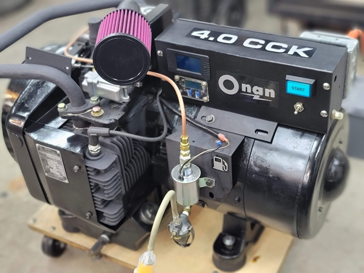
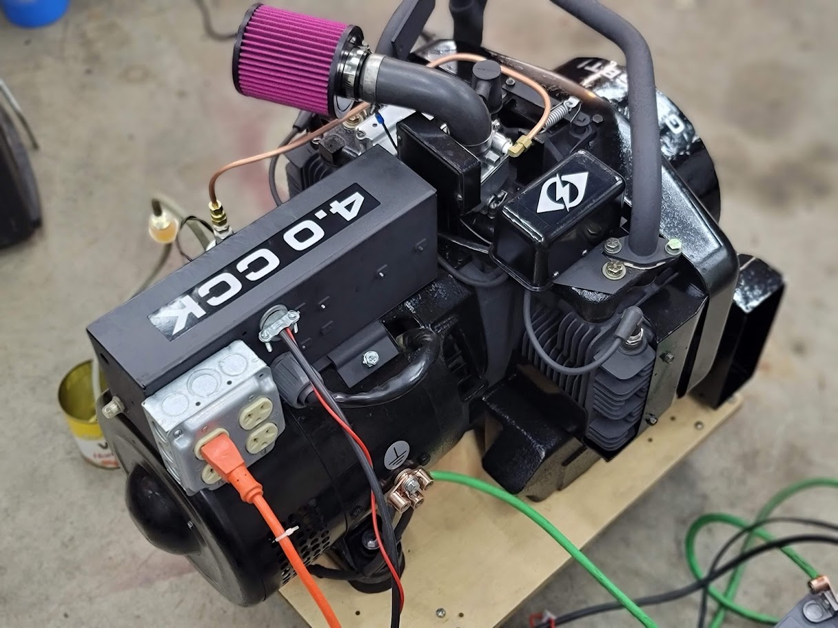
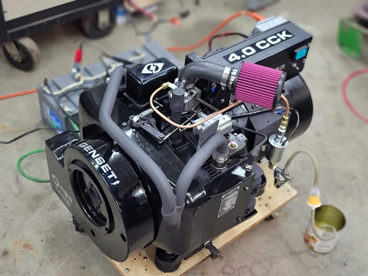
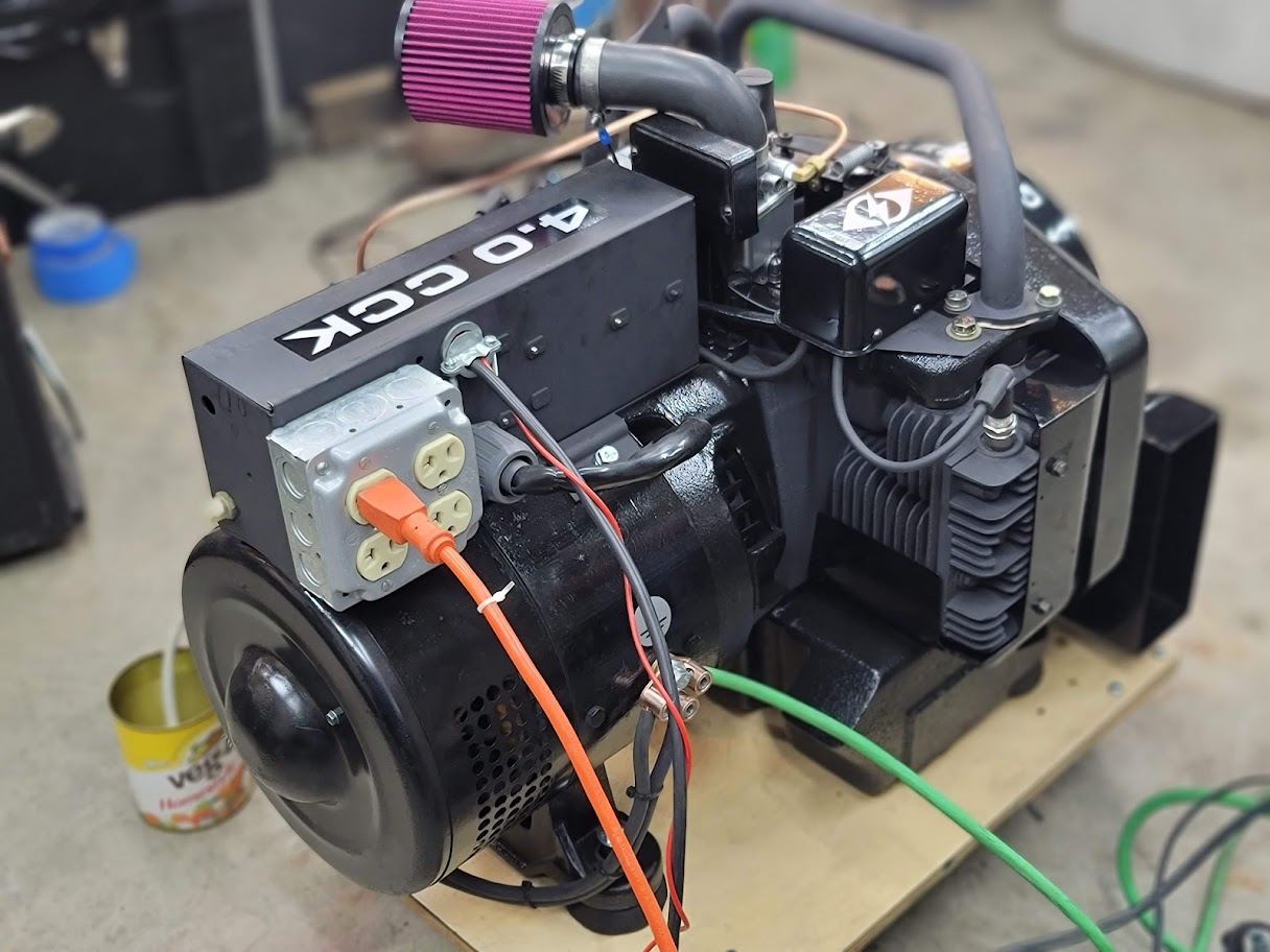
And here it is in all its new decal glory. What a difference a few stickers can make! Has a more modern look to an old 1970’s generator.
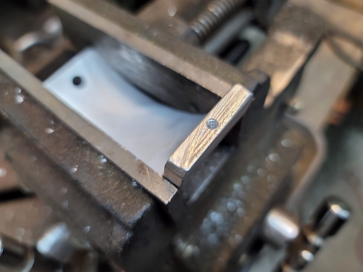
After an afternoon of fine tuning, I was able to get to this stage, The volt scale on the cheap meter is a bit off ( High ) so with a real voltmeter I was able to verify the generator falls within the spec, 57-63Hz and 102-132VAC that most UPS units need to see. And within spec of the Onan manual, 57-64Hz and 110-126VAC So for now I think I am good on adjustments. Had to make a new Governor adjustment screw with a bit more adjustment range after the old one broke on me. ( Was a bit too far gone from rust I guess )
The last and Final stop will be the Exhaust, finding a 1.5″ OD Exhaust pipe clamp ( smooth style ) is proving tricky, but will get on that project next. Thanks for hanging in so far on this project! Please let me know your thoughts or questions in the comments below!
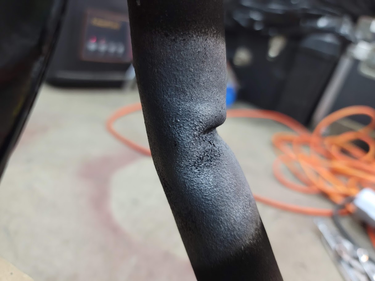

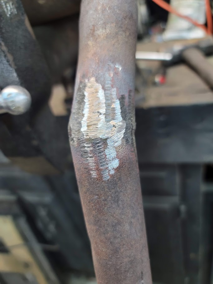
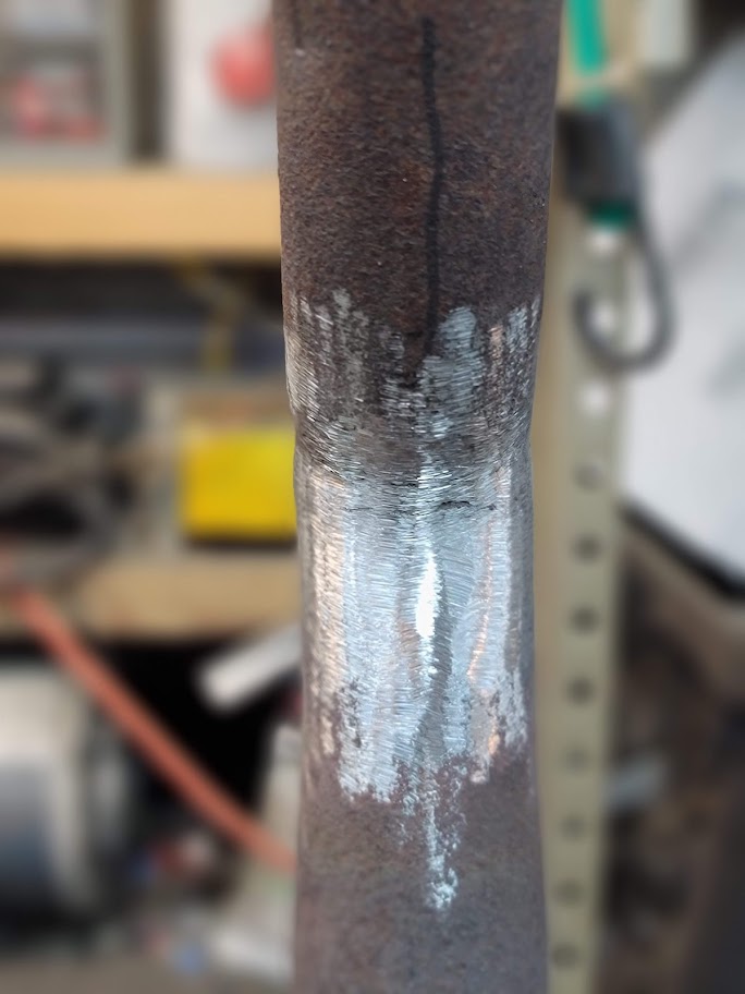
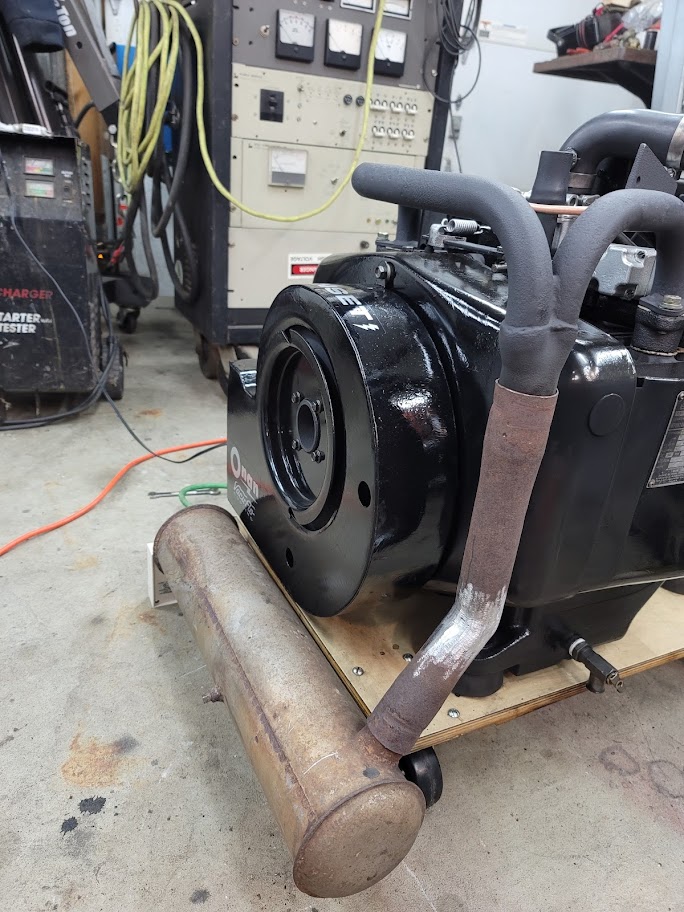
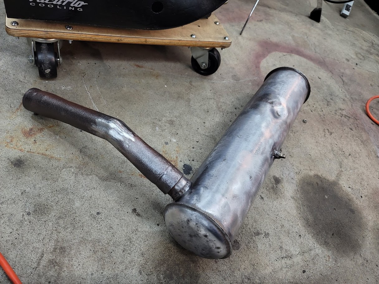
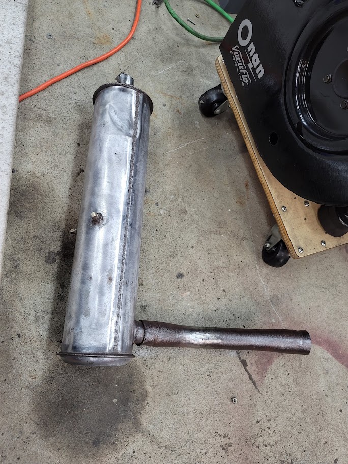
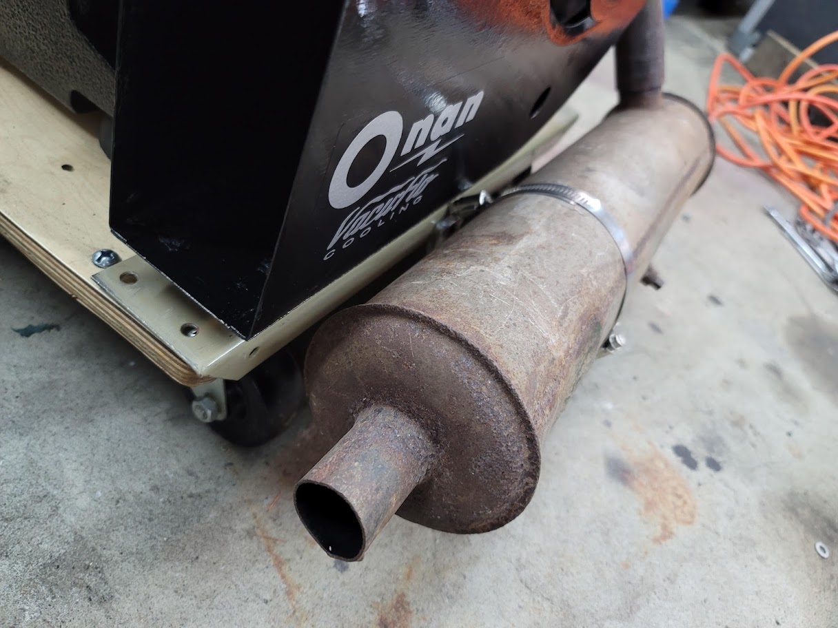
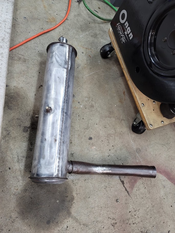
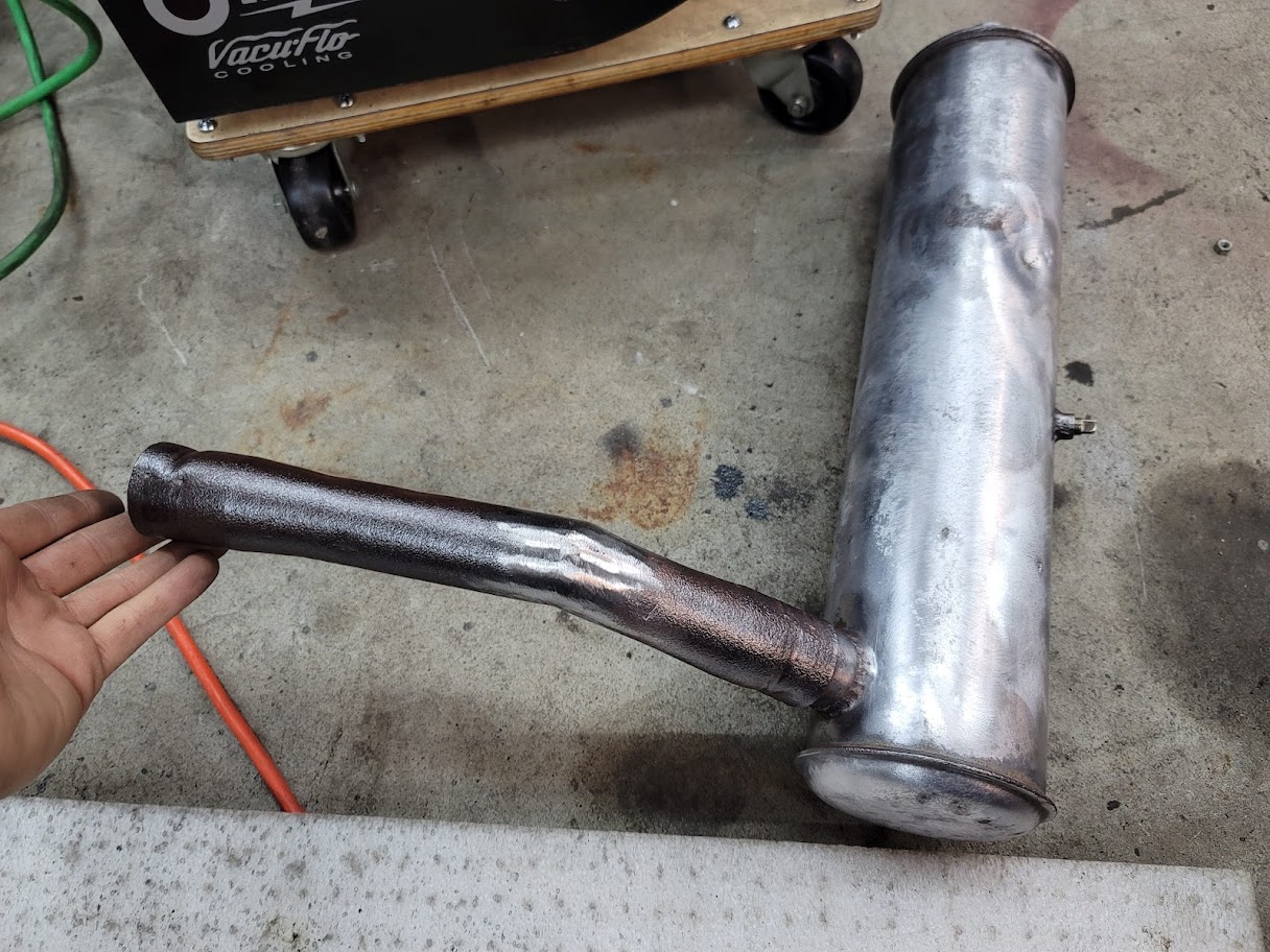
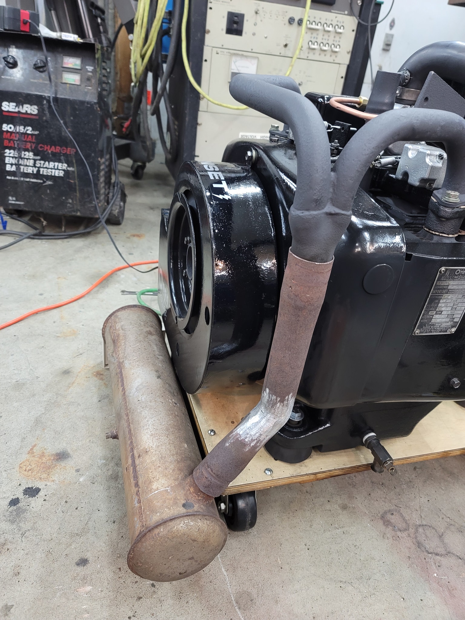
I tried to heat bend the old tube, but it was too old and rusty, it just caved like tin foil, so had to cut it and weld in the angle. Turned out pretty nice, next step was to get it into paint. The muffler was the final strew my angle grinder went up in flames, what a fitting end to the project ha!
UPDATE: 2/14/2022 It is DONE!!
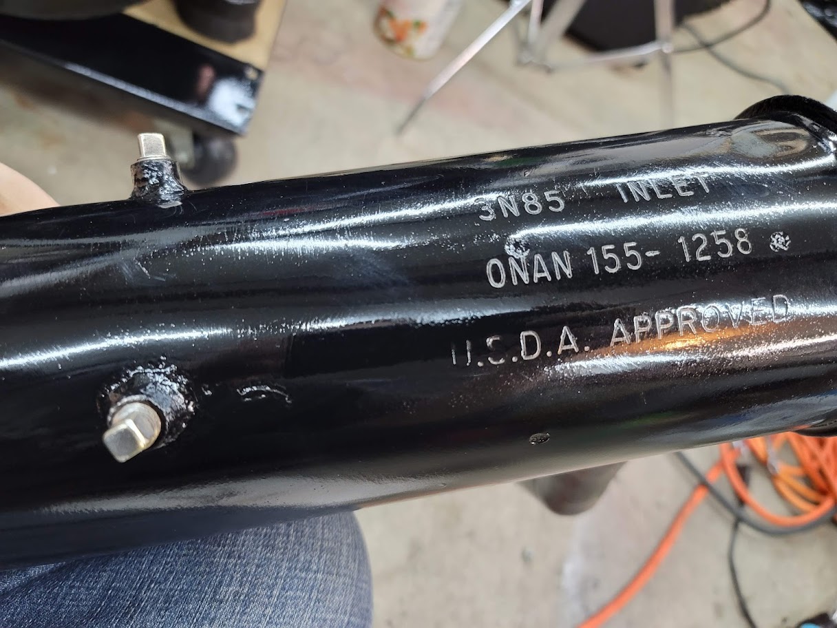
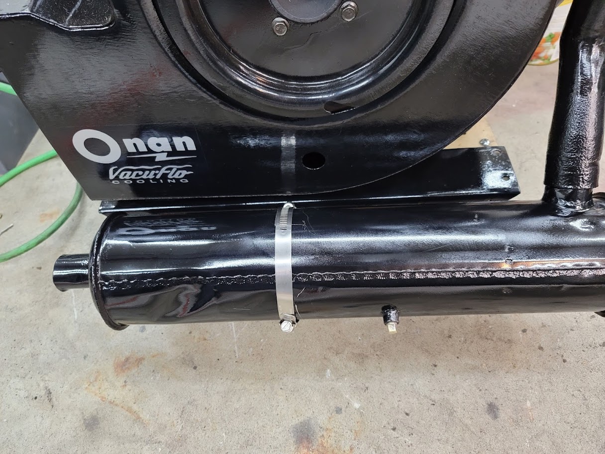
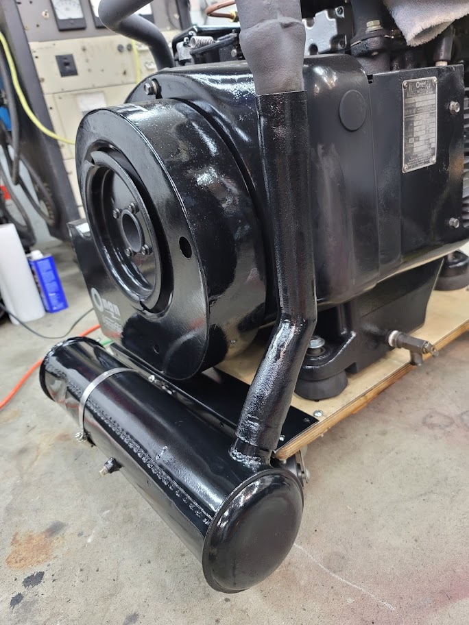
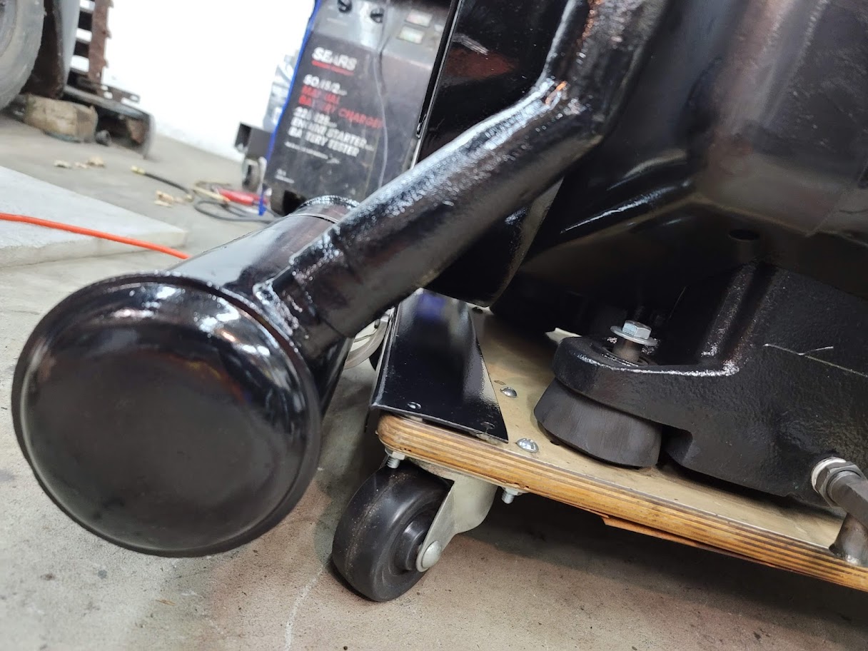
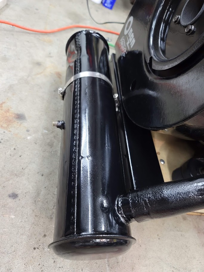
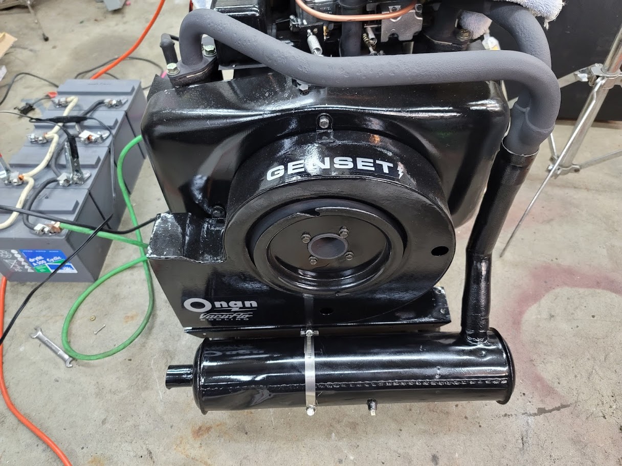
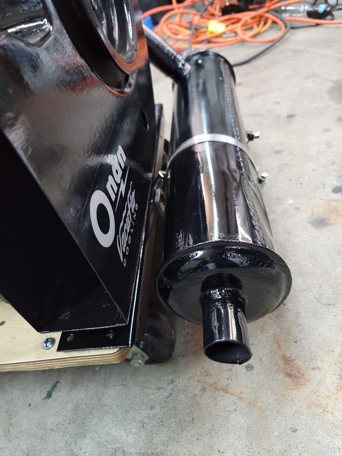
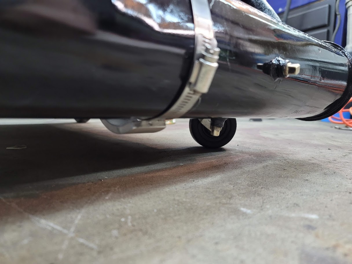
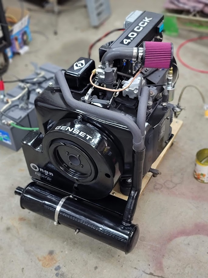
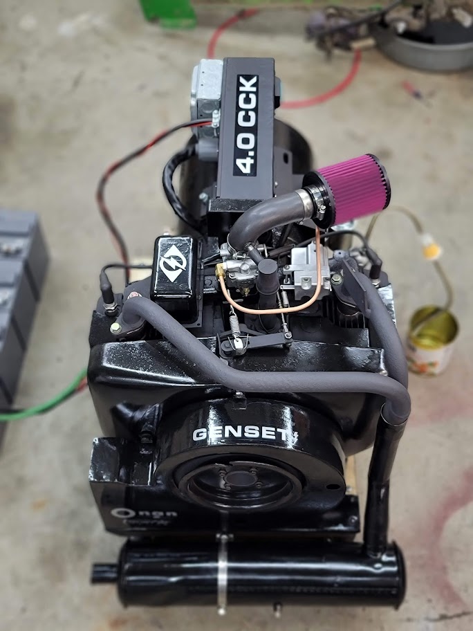
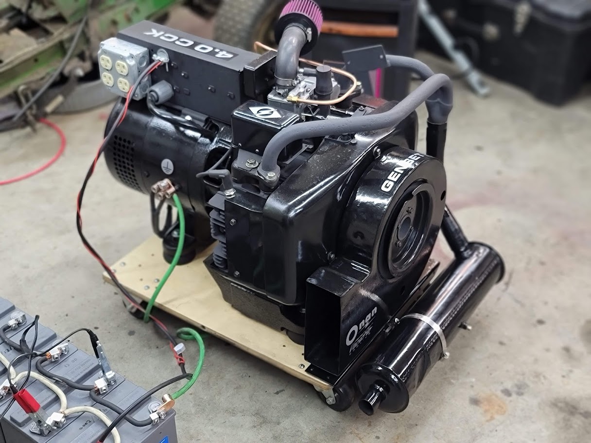
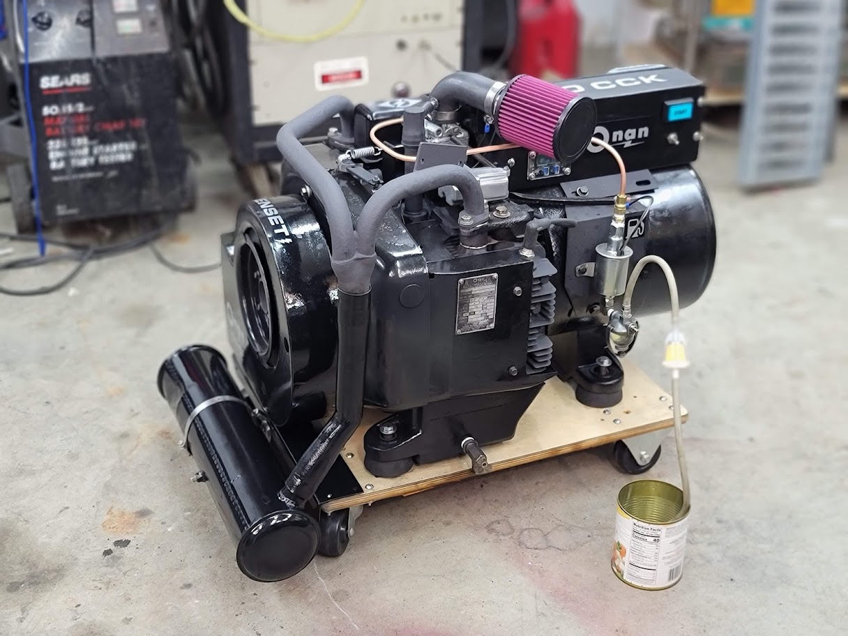
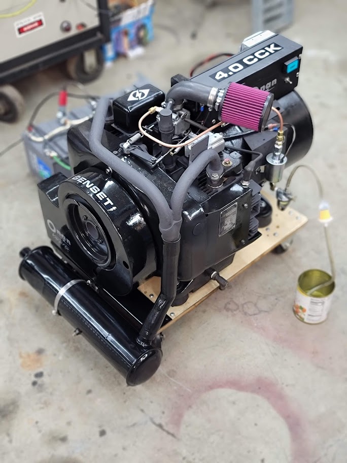
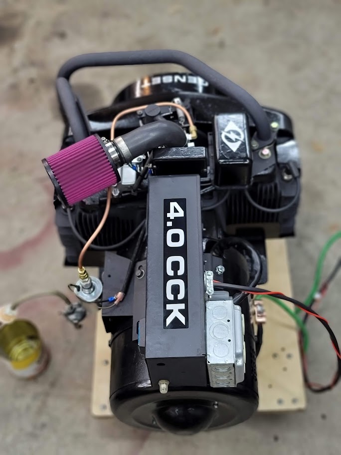
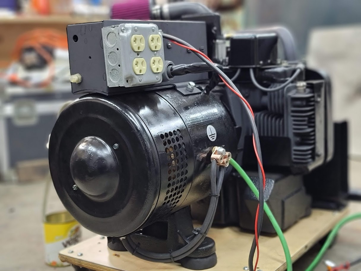
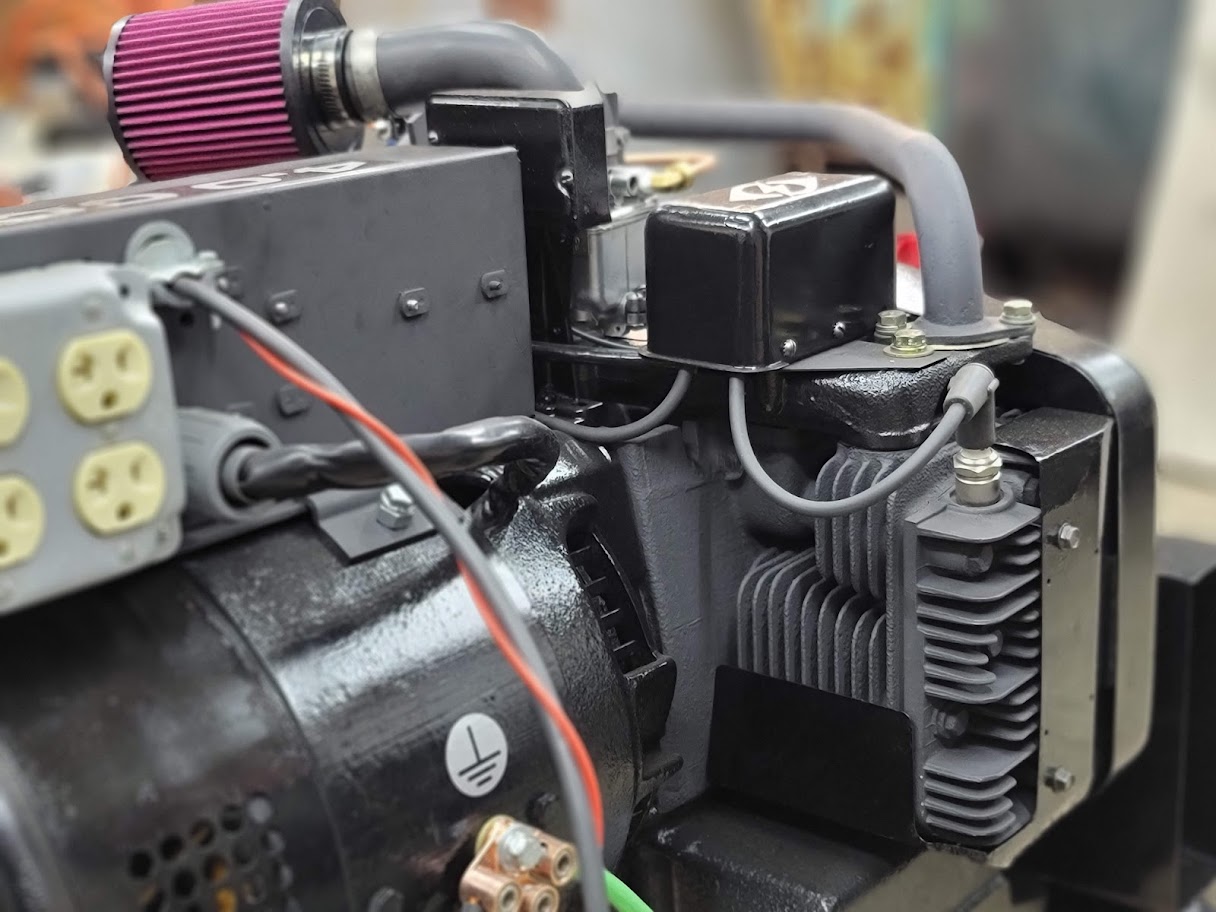
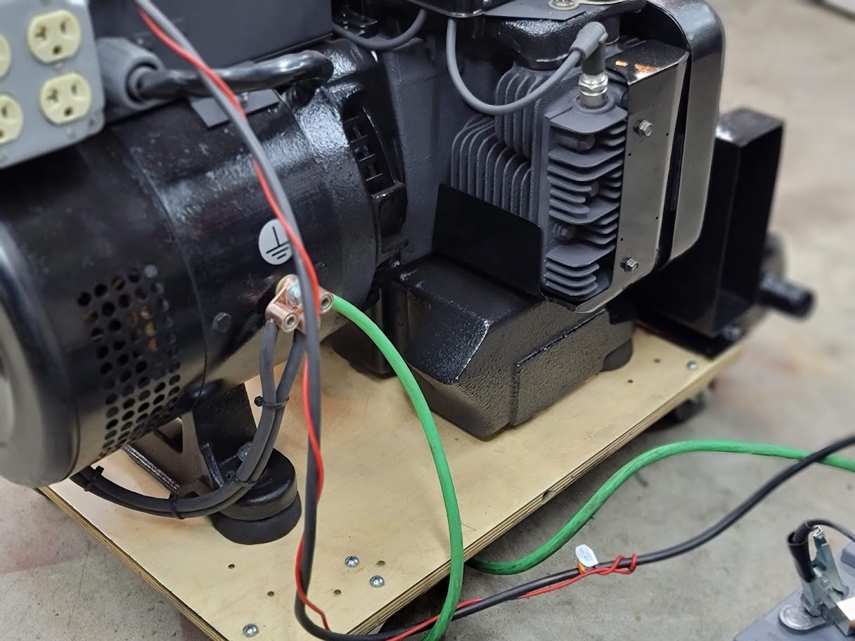
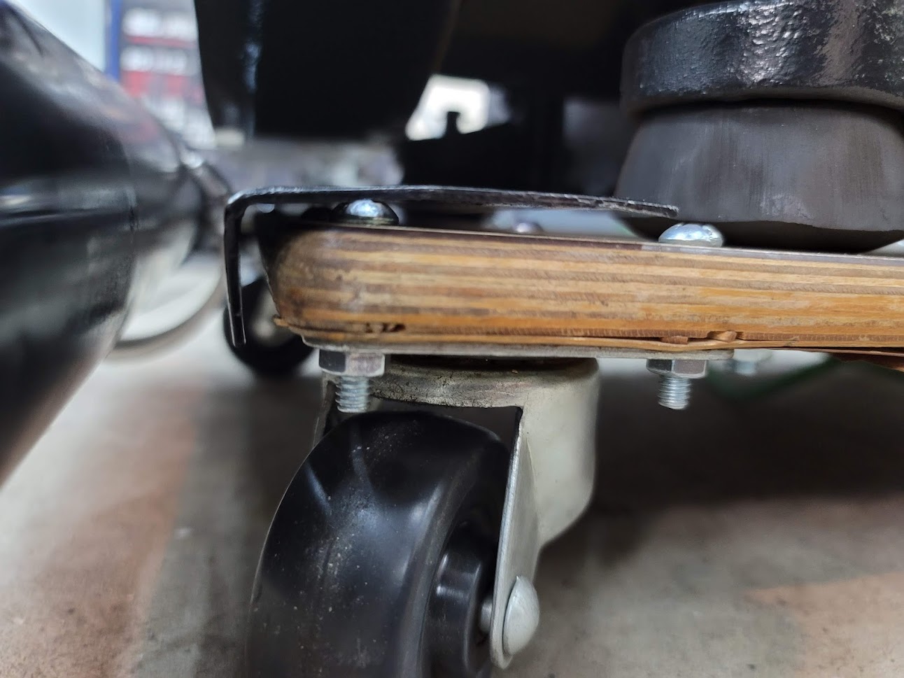
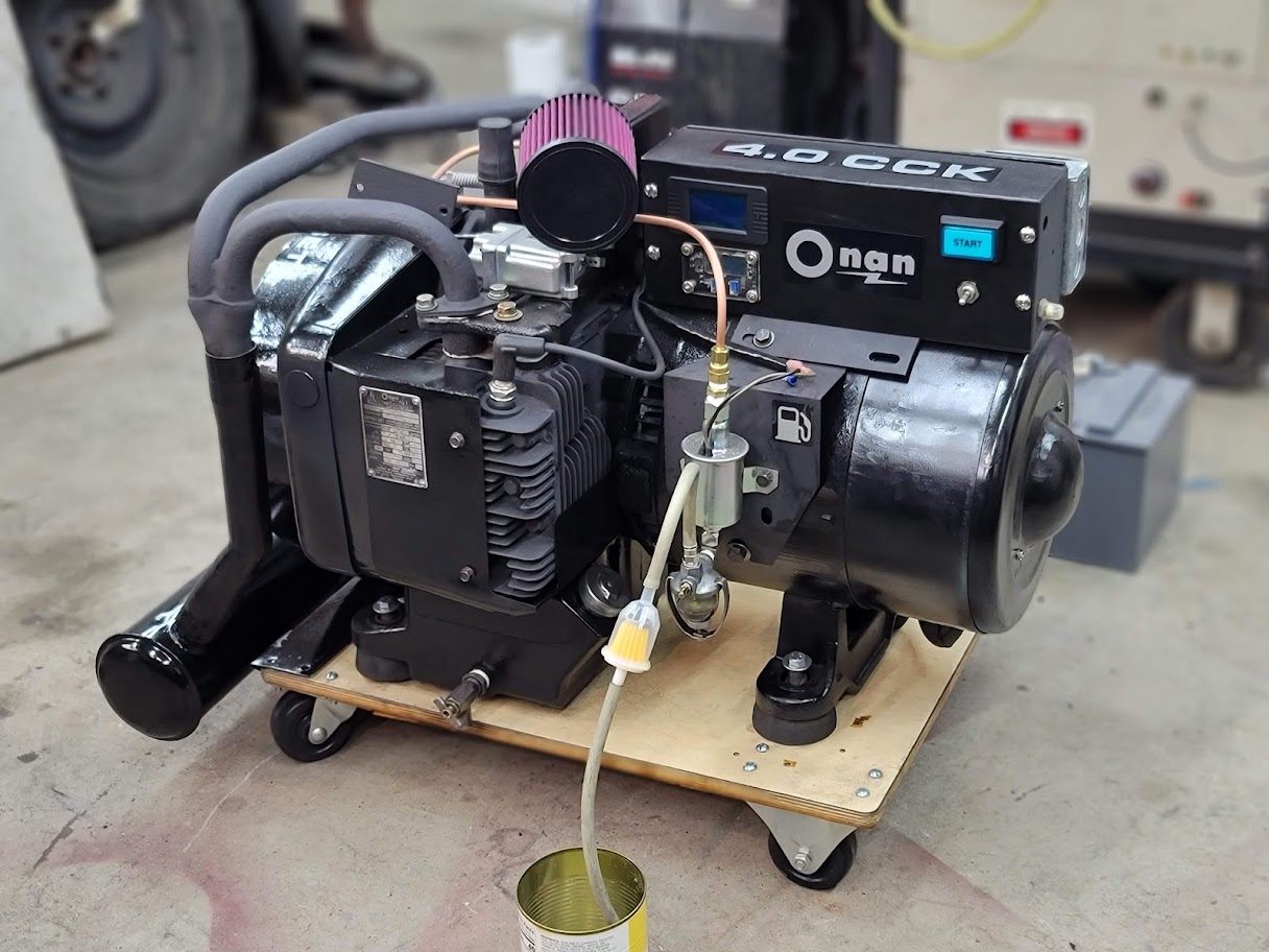
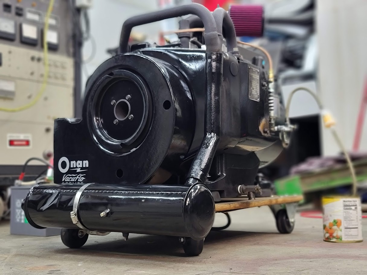
Man does it feel good to be done with this one!
Thanks to all of you who have read this far and followed along with this project! There are still small things to finish up like the exhaust clamp, new fuel line, new cart, and fine adjustments. But I will call this project complete! On your way back be sure to look at the top of this page to see how far it has come!
~Cheers
Here is a 45 min time lapse with my thermal cam to see how well the cooling system works, and if the cylinders are load balanced. All looks good! New cart also works very well.
UPDATE: 5/14/2023 Generator has been used a few times now when the power has gone out, and it has performed perfectly! And much more silent than my neighbors higher RPM modern generators!
Here are some links to the Manuals I used on this project, NOTE: I never found the exact manual for mine, for that would have been part of the RV manual it was built into, so these got me close enough for what I needed!
https://www.djdlabs.com/Onan_opp_manual.pdf
https://www.djdlabs.com/9270310Onan4KW5KWCCKRVGensetOperatorsmanualPartscatalog061971.3838681500.pdf
https://www.djdlabs.com/927-0006%20Onan%20CCK%20(spec%20A-F)%20Genset%20Instruction%20manual.pdf
Many more manuals can be found here ( Outside link )
http://www.skilledcrafting.com/onanfiles/
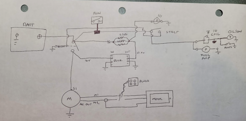
UPDATE: 9/7/2024 I have received a few requests on how I wired my new control box, here is a crude wire diagram, let me know if you need me to re-draw it more proper. This was just a sketch for me when I was building it.
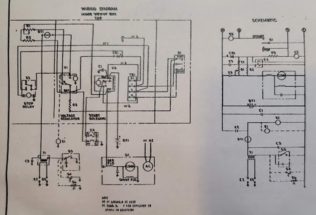
LEFT: How it was wired from ONAN / CENTER: How I wired my new box / RIGHT inside view before I wired it into the generator wires.
S1: The big red + wire into the motor to both start it and get power back to charge the battery. M1 and M2 are the 120V output from the generator. I ran them through a 30Amp breaker and to the outlet box. The start button has a 12V lamp installed. Will try and find link to items used and link them bellow.
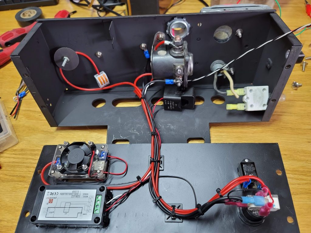
METER: https://www.amazon.com/gp/product/B07WZMYFV9/ref=ppx_yo_dt_b_search_asin_image?ie=UTF8&psc=1
Buck converter: NOTE: do not use this, it did not work for this install and died quick, a proper battery charger would work good here.
https://www.amazon.com/gp/product/B07JZ2GQJF/ref=ppx_yo_dt_b_search_asin_image?ie=UTF8&th=1
Starter relay: https://www.amazon.com/AFEISOL-4-Terminal-Compatible-B-6A-11450A-D2AF11450AA/dp/B0CNGRCTPS/
30Amp circuit breaker: https://www.amazon.com/COOPER-BUSSMANN-PANEL-CIRCUIT-BREAKER-CB174-30/dp/B01F2O7VKA/
Possible start button, I used an old arcade button. https://www.amazon.com/weideer-Starter-Ignition-Momentary-K-M042-BU-DZ/dp/B0CZ8P3HTV/
Any questions please leave them in the comments below!




Fascinating project for sure. The inside of an old electric motor, etc. Who knew?
The restoration procedure, organization of parts, and cleaning and painting are extremely interesting.
Love the detailed pictures. If anyone wants to learn…this is the place.
Great work! Great organizational skills!
Keep em coming!
4.0cck The controll box has 12v coming in and the wires from the can going in . and then where do the other three wires go coming out of the box . one is to oil shut of and then ?
Page #26 here may help you out.
https://web.archive.org/web/20120526114931/http://www.cumminsonan.com/www/pdf/manuals/900-0196.pdf
Depending on the features yours has, Mine had (Ignition coil power ) ( 120V out ) ( remote turn on/shutoff ) ( Oil pressure switch was tied to ignition points, it would hold ground and prevent spark if no oil pressure )
A1 ……. Generator Set Control Assembly
A2 ……. Start Adapter Control (4 to 3 wire)
A3 ……. Disconnect Adapter Control
BT1. ….. Battery
El ……. Fuel Pump or Gas Valve (When Used)
E2,E3 …. Spark Plug
E4.. ….. Electric Choke (When Used)
G1 ……. Generator
K1 ……. Start Solenoid Relay
K2.. ….. Fuel Solenoid (When Used)
S1 ……. Low Oil Pressure Switch (When Used)
S2 ……. High Air Temperature Switch (When Used)
S3 ……. Breaker and Cap Assembly
S4 ……. Remote Start-Stop Switch (Customer Remote)
S5 ……. Vacuum Switch (When Used)
T1 ……. Ignition Coil
AlSl ….. Hand Crank – Electric Start Switch
AlS2. …. Start-Stop Switch
Any questions let me know!
Awsome job. I restore and build early Ford Street rods. Nice work. Have same unit and wondered where you got ign. And carb parts? I am going thru mine and want spares if needed.
Thank you! Working on a 51 Chevy truck now!
For the ignition coil and wires, I found this worked
https://www.amazon.com/gp/product/B079HT4XC3/
It also fit under the stock cover.
The wires,
https://www.amazon.com/gp/product/B083D9QFHG/
For the carb I went to ebay, not everything fit, but it had most of what I needed, I re used my stock needle.
https://www.ebay.com/itm/165677242634
Any questions feel free to reply!
Good luck with your project!
Where were you able to track down a manual and parts? I just picked this same unit up for $75 today and plan to use it to run parts of my house through a transfer switch.
I found the manuals across much of the internet, for this exact model was built as part of an RV so would have been serviced by them. I update the bottom of this page to have links to all the manuals I used! Hope that helps you and others who visit.
Here is a direct link to a large collection of Onan manuals, http://www.skilledcrafting.com/onanfiles/
The folks over at the SmokStack.com forum, where a huge help with finding info, worth reaching out to them as well! Here is a link to my project thread. With lots of info and links from them.
https://www.smokstak.com/forum/threads/4-0-cck-restoration-project.220621/
Any questions let me know! These are great units you will love it!
Wow! Nice work. I’ll be clicking on all the related links you have, looking for more info on my Generator. It’s a 4kw like yours, same era I believe. But it’s a diesel marine unit. Not having luck finding much info on it. I am thinking about doing an updated control like you’ve done. Though, not sure I have the skillset…
Thank you! and Best of luck on your generator project! Lots of info in the links I shared, if you have any questions as you go, post up a comment, happy to help!
Hi ! i would like to make the same control box can you help with the parts you used and wiring diagram
Eric, Happy to help! The main parts are a starter relay, a toggle switch and a momentary push button. This is the bare minimum to start and run it. The Charge controller did not last long for me, so would not recommend. I ended up just taking the battery charger/maintainer that is always connected to the battery, and just plug it into the generators output, when it is running to keep the battery topped off. Does not need much for it is only running a fuel pump and 2 spark plugs. I will work on a wire diagram and post it up above when done! NOTE: I do not have any of the ‘smart’ features in use on mine, the auto choke, and auto battery charger/regulate, and remote start/auto run. I will always be standing at it to start it, so was not worries about those extra features. I manually choke it until it starts than open the choke and let it run.
I have update the page above with some drawings, parts lists and my comments, let me know if you have any questions!